Rotor and manufacturing method of arc magnet for rotor

a technology of arc magnet and manufacturing method, which is applied in the direction of magnetic circuit rotating parts, dynamo-electric machines, and magnetic circuit shape/form/construction, etc., can solve the problem of decreasing the permeance coefficient of the entire arc magnet, and achieve the effect of suppressing the demagnetization of the arc magnet, improving the permeance coefficient of the entire arc magnet, and convenient demagnetization

Inactive Publication Date: 2020-06-11
HONDA MOTOR CO LTD
View PDF0 Cites 0 Cited by
  • Summary
  • Abstract
  • Description
  • Claims
  • Application Information

AI Technical Summary

Benefits of technology

[0008]According to the present invention, since the wall thickness of both end portions in the circumferential direction of the outer peripheral surface of the arc magnet that is easily demagnetized is increased, demagnetization of the arc magnet can be suppressed, and further, the permeance coefficient of the entire arc magnet can be improved.

Problems solved by technology

In the rotor of JP-A-H09-233744, demagnetization occurs at both end portions in the circumferential direction of the outer circumferential surface of the arc magnet, which causes a problem that the permeance coefficient of the entire arc magnet decreases.

Method used


Image

  • Rotor and manufacturing method of arc magnet for rotor
  • Rotor and manufacturing method of arc magnet for rotor
  • Rotor and manufacturing method of arc magnet for rotor

Examples


Embodiment Construction

[0014]Hereinafter, an embodiment of a rotor of the present invention will be described with reference to the accompanying drawings.

[Overall Configuration of Rotor]

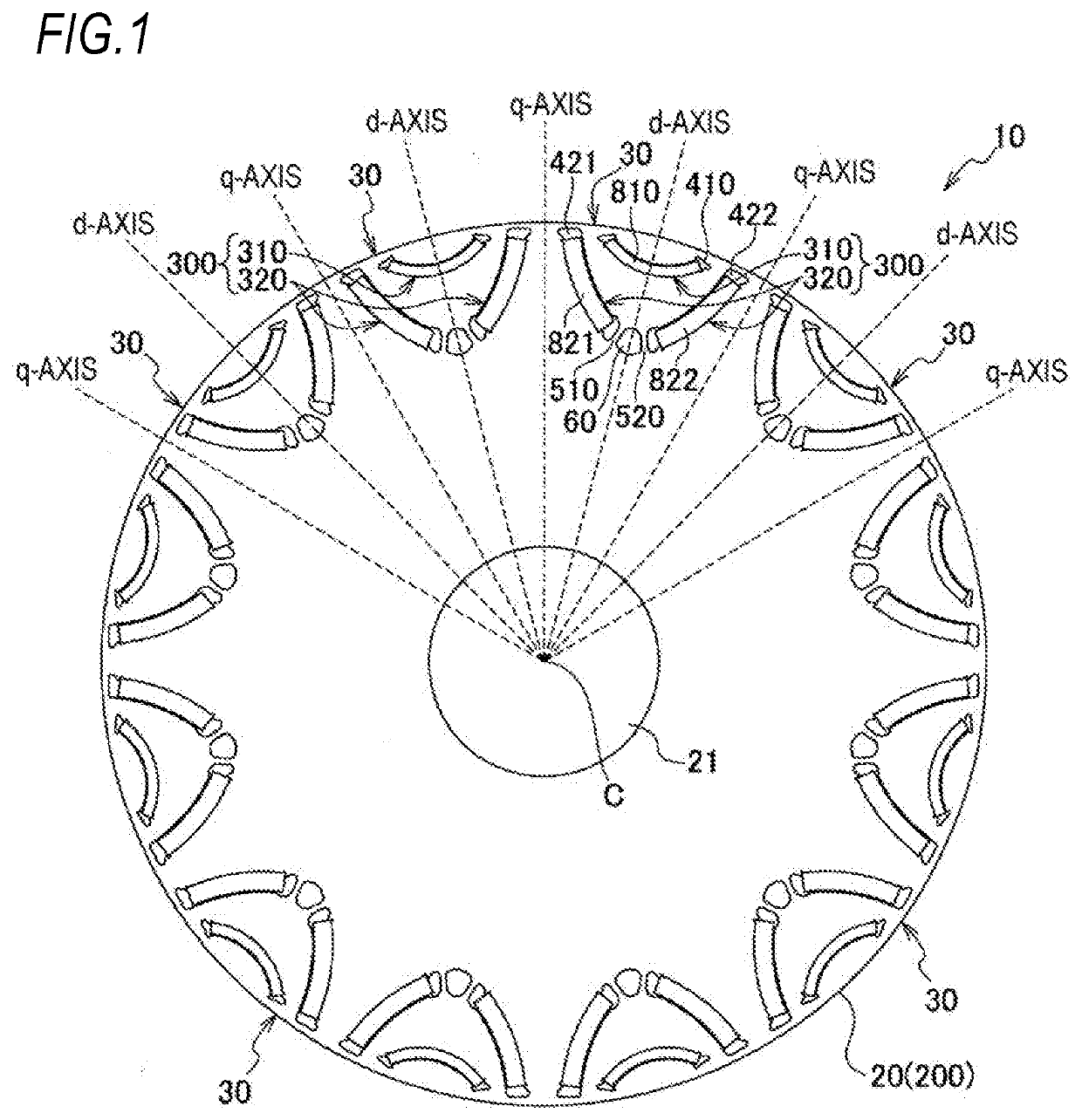
[0015]As illustrated in FIG. 1, a rotor 10 of a rotating electrical machine of one embodiment includes a rotor core 20 attached to an outer peripheral portion of a rotor shaft (not illustrated), and a plurality of magnetic pole portions 30 (12 in this embodiment) formed inside the rotor core 20 at predetermined intervals in the circumferential direction, and the rotor 10 is arranged on the inner peripheral side of a stator (not illustrated).

[0016]The rotor core 20 is formed by laminating a plurality of substantially annular electromagnetic steel plates 200 having the same shape in the axial direction. The rotor core 20 includes a rotor shaft hole 21 concentric with an axial center C. Furthermore, when the central axis of each magnetic pole portion 30, which connects the axial center C and the center of each magnetic pole p...


PUM


Abstract

A rotor includes: a rotor core including a plurality of magnet insertion holes provided along the circumferential direction; and a plurality of magnetic pole portions constituted by arc magnets inserted into the magnet insertion holes. The arc magnet, constituting each magnetic pole portion, is arranged to protrude inward of the rotor core in the radial direction, and has thick portions protruding to the outer peripheral surface at both circumferential end portions of the outer peripheral surface.

Description

CROSS-REFERENCE TO RELATED APPLICATIONS[0001]The present application claims the benefit of priority of Japanese Patent Application No. 2018-231024, filed on Dec. 10, 2018, the content of which is incorporated herein by reference.TECHNICAL FIELD[0002]The present invention relates to a rotor used in a rotating electrical machine and a manufacturing method of an arc magnet for a rotor.BACKGROUND ART[0003]In the related art, as a rotor used in a rotating electrical machine, a rotor in which a plurality of permanent magnets are arranged at predetermined intervals in the circumferential direction inside a rotor core is known. For example, JP-A-H09-233744 discloses a rotor for a rotating electrical machine, which includes a magnetic pole portion in which an arc magnet located on the outer diameter side of the rotor and an arc magnet located on the inner diameter side of the rotor have substantially the same plate thickness and are arranged in a substantially concentric circle shape.[0004]I...

Claims


Application Information

Patent Timeline
Patent Type & Authority Applications(United States)
IPC IPC(8): H02K1/27H02K15/03
CPCH02K1/2766H02K15/03H02K1/276
Inventor SOMA, SHINGOKUBOTA, YOSHIHISAOHZU, TATSUYA
Owner HONDA MOTOR CO LTD
Why Eureka
Try Eureka