
A stirring bar to prevent contamination

A technology for preventing contamination and stirring bars, applied in mixers, dissolving, chemical instruments and methods, etc., can solve the problems of affecting uniform distribution, affecting reaction results, contaminating the chemical synthesis process, etc., achieving easy demagnetization, low coercivity, The effect of high permeability

Active Publication Date: 2021-08-31
MINJIANG UNIV
View PDF4 Cites 1 Cited by
  • Summary
  • Abstract
  • Description
  • Claims
  • Application Information

AI Technical Summary

Problems solved by technology

[0003] The magnetic stirrer has the advantages of simple structure and small volume, but the current stirrer is mainly composed of a permanent magnetic core and a polymer material wrapped outside, which causes the stirrer to be adsorbed on the surface during storage and use. Magnetic dust particles such as iron, nickel, cobalt and their alloys pollute the chemical synthesis process
In addition, in biological experiments, pharmaceutical separation and purification, and material and substance analysis, the existence of these fine dust particles will seriously affect the accuracy of experiments, thus limiting the application of magnetic stirrers in these fields
[0004] On the other hand, the reaction system itself contains iron, nickel, cobalt and its alloys and other reaction raw materials. During the reaction process, due to the magnetic attraction of the stirrer, these raw materials are adsorbed and enriched on the surface of the stirrer, which affects the reaction of these raw materials. The uniform distribution of the entire reaction system ultimately affects the reaction result

Method used


Image

  • A stirring bar to prevent contamination
  • A stirring bar to prevent contamination
  • A stirring bar to prevent contamination

Examples


Embodiment 1

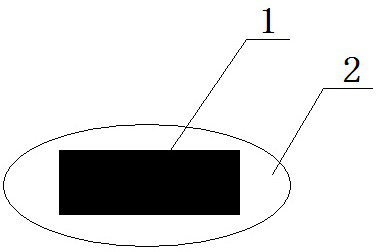
[0019] figure 1 It is a schematic diagram of a polytetrafluoroethylene-wrapped silicon steel core stirrer prepared by molding. Tetrafluoroethylene powder, then place the silicon steel core and add the rest of the powder. Put the mold on the press, press the required 500kg / cm 2 The pressure is slowly increased, and the pressure should be properly exhausted during the pressurization process, and after reaching the specified pressure, it is generally maintained for 12 minutes. Place the pressed stirrer blank in the sintering furnace as required, close the furnace door, and heat up to 350°C to sinter the blank for 5 minutes. Cool, shape and remove the burrs to obtain a polytetrafluoroethylene-wrapped silicon steel core stirring bar.

Embodiment 2

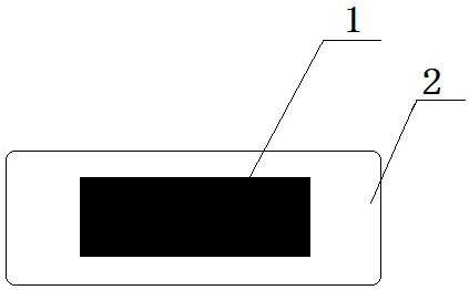
[0021] figure 2 It is a schematic diagram of a stirrer with a nickel-iron-permalloy core wrapped in tetrafluoroethylene-hexafluoropropylene copolymer prepared by thermoforming. The preparation process is as follows: insert the nickel-iron-permalloy core into the tetrafluoroethylene-hexafluoropropylene copolymer In the material tube, heat to 300 ° C for 2 minutes to soften the polymer tube and vacuumize at the same time. Under vacuum conditions, the softened polymer is tightly wrapped on the surface of the permalloy core, and finally both ends are heated and fused to remove the burrs to obtain a tetrafluoroethylene-hexafluoropropylene copolymer-wrapped nickel-iron permalloy core stirring bar.

Embodiment 3

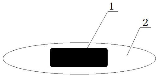
[0023] image 3 It is a schematic diagram of the glass-wrapped amorphous iron-nickel alloy core stirrer prepared by the hot melting method. The preparation process is as follows: the high temperature glass melt taken out of the hot melting furnace is inserted into the amorphous iron nickel alloy core, and the alloy is processed The core is completely wrapped in glass, placed in a stirrer mold while it is hot, and slowly cooled to obtain a glass-wrapped amorphous iron-nickel alloy core stirrer.


PUM


Abstract

The invention provides a stirring bar for preventing pollution. The stirring bar is composed of a stirring bar core and an outer covering layer. Among them, the stirrer core is made of soft magnetic material, and the outer cladding layer is made of polymer or glass material. The stirrer core and the outer covering material are prepared by hot melting, molding and thermoforming. The soft magnetic material used in the stirrer core is easy to magnetize and demagnetize. The stirrer rotates and stirs under the magnetic field of the magnetic stirrer. When the stirring is stopped and the magnetic field is left, all or most of the magnetism obtained will disappear, thus avoiding There are magnetic impurities such as iron, nickel, cobalt and their alloys adsorbed on the surface of the stirrer during storage and use to pollute chemical synthesis, biological experiments, pharmaceutical separation and purification, and material and substance analysis processes.

Description

technical field [0001] The invention relates to the field of experimental equipment, in particular to a stirring bar for preventing pollution. Background technique [0002] Magnetic stirrer is a common experimental device in the fields of biology, chemistry, medicine, materials and substance analysis. A commonly used magnetic stirrer consists of a motor and a turntable with a permanent magnet, and is used in conjunction with a magnetic stirrer during work. The principle is to use the rotation of the motor to drive the turntable to rotate. The magnet installed on the turntable generates a rotating magnetic field during the rotation process. The magnetic stirrer inside the experimental container drives the medium in the container to undergo forced convection under the action of the rotating magnetic field to achieve uniform mixing. Purpose. [0003] The magnetic stirrer has the advantages of simple structure and small volume, but the current stirrer is mainly composed of a p...

Claims


Application Information

Patent Timeline
Patent Type & Authority Patents(China)
IPC IPC(8): B01F13/08
Inventor 马良
Owner MINJIANG UNIV
Learn More