R-t-b based sintered magnet

a sintered magnet and r-t-b technology, applied in the field of r-t-b based sintered magnets, can solve the problems of reducing the size of the resultant metallurgical structure reducing the size of the resultant metallurgical structure, and increasing the requirements of the ferromagnetism of the sintered body. it can promote the sintering reaction, improve the loop squareness of the demagnetization curve, and increase the coer

Active Publication Date: 2010-01-14
HITACHI METALS LTD
View PDF3 Cites 2 Cited by
  • Summary
  • Abstract
  • Description
  • Claims
  • Application Information

AI Technical Summary

Benefits of technology

[0029]If an R-T-B based sintered magnet includes Pr as an essential element and an additive Mn in an amount that falls within a predetermined range, its coercivity at around room temperature can be increased and higher coercivity than conventional magnets' can be achieved even at high temperatures of 80° C. or more. Also, by adding a predetermined amount of Mn, the sintering reaction can be promoted during the manufacturing process of the sintered magnet. As a result, the sintering process can be done either at a lower temperature or in a shorter time and the sintered magnet can have a homogenized structure. Consequently, the loop squareness of the demagnetization curve can be improved as well.

Problems solved by technology

And their requirements are becoming increasingly severe nowadays.
One of the old drawbacks of R-T-B based magnets is their relative low Curie temperature of approximately 300° C., at which their ferromagnetism is lost.
Furthermore, the additive elements such as Ti, V, Cr, Zr, Nb, Mo, Hf and W disclosed in Patent Document No. 5, for example, hinder the growth of crystal grains during the sintering process and reduce the size of the resultant metallurgical structure of the sintered body, thus contributing to increasing the coercivity.
According to any of the other methods mentioned above, however, a significant decrease in the magnetic flux density of the magnet is inevitable.
However, those heavy rare-earth elements such as Dy and Tb are among the rarest and expensive ones of all rare-earth elements.
For that reason, if a lot of such heavy rare-earth elements should be used, then the price of the magnets would rise.
In addition, as the applications of such R-T-B based sintered magnet have been rapidly expanding these days, resource-related restrictions on those heavy rare-earth elements have become an issue these days because those rare elements are available only in very limited quantities and in very narrow areas.
Also, as mentioned above, none of those methods is so effective by itself and each of them would generally result in a significant decrease in the magnetic flux density of the magnet.
That is why it has been very difficult to increase the coercivity without using any heavy rare-earth element.

Method used


Image

  • R-t-b based sintered magnet
  • R-t-b based sintered magnet
  • R-t-b based sintered magnet

Examples


example 1

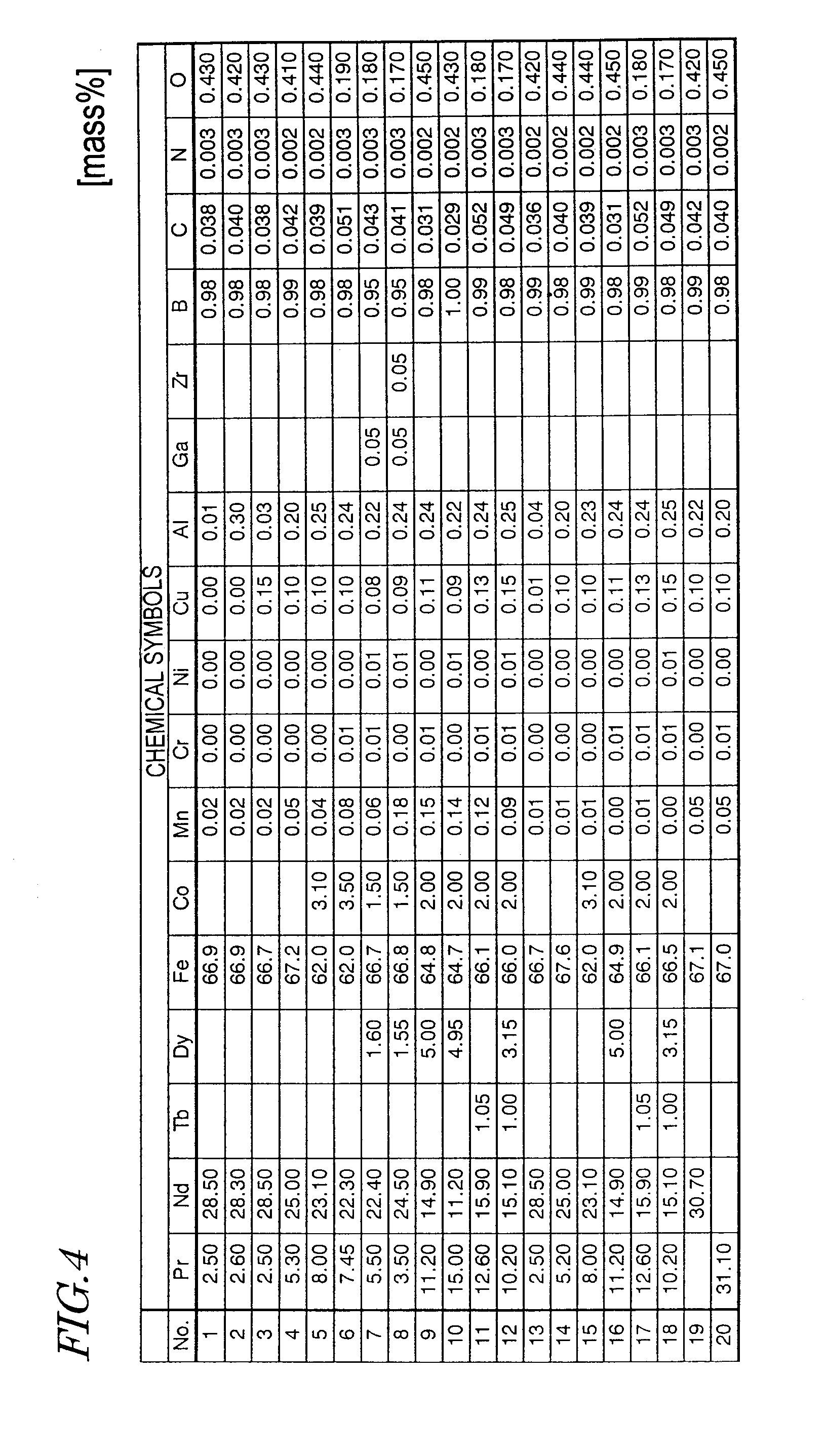
[0083]An alloy with an objective composition was prepared by mixing together Pr and Nd with a purity of 99.5% or more, Tb and Dy with a purity of 99.9% or more, electrolytic iron, and low-carbon ferroboron alloy together with the other objective elements added in the form of pure metals. The alloy was then melted and cast by a strip casting process, thereby obtaining a plate-like alloy with a thickness of 0.3 mm to 0.4 mm.

[0084]This material alloy was subjected to a hydrogen decrepitation process within a hydrogen atmosphere with an increased pressure, heated to 600° C. in a vacuum, cooled and then classified with a sieve, thereby obtaining a coarse alloy powder with a particle size of 425 μm or less. Then, zinc stearate was added to, and mixed with, this coarse powder so as to account for 0.05 mass % of the powder.

[0085]Next, the coarse alloy powder was subjected to a dry pulverization process using a jet mill machine in a nitrogen gas flow, thereby obtaining a fine powder with a p...

example 2

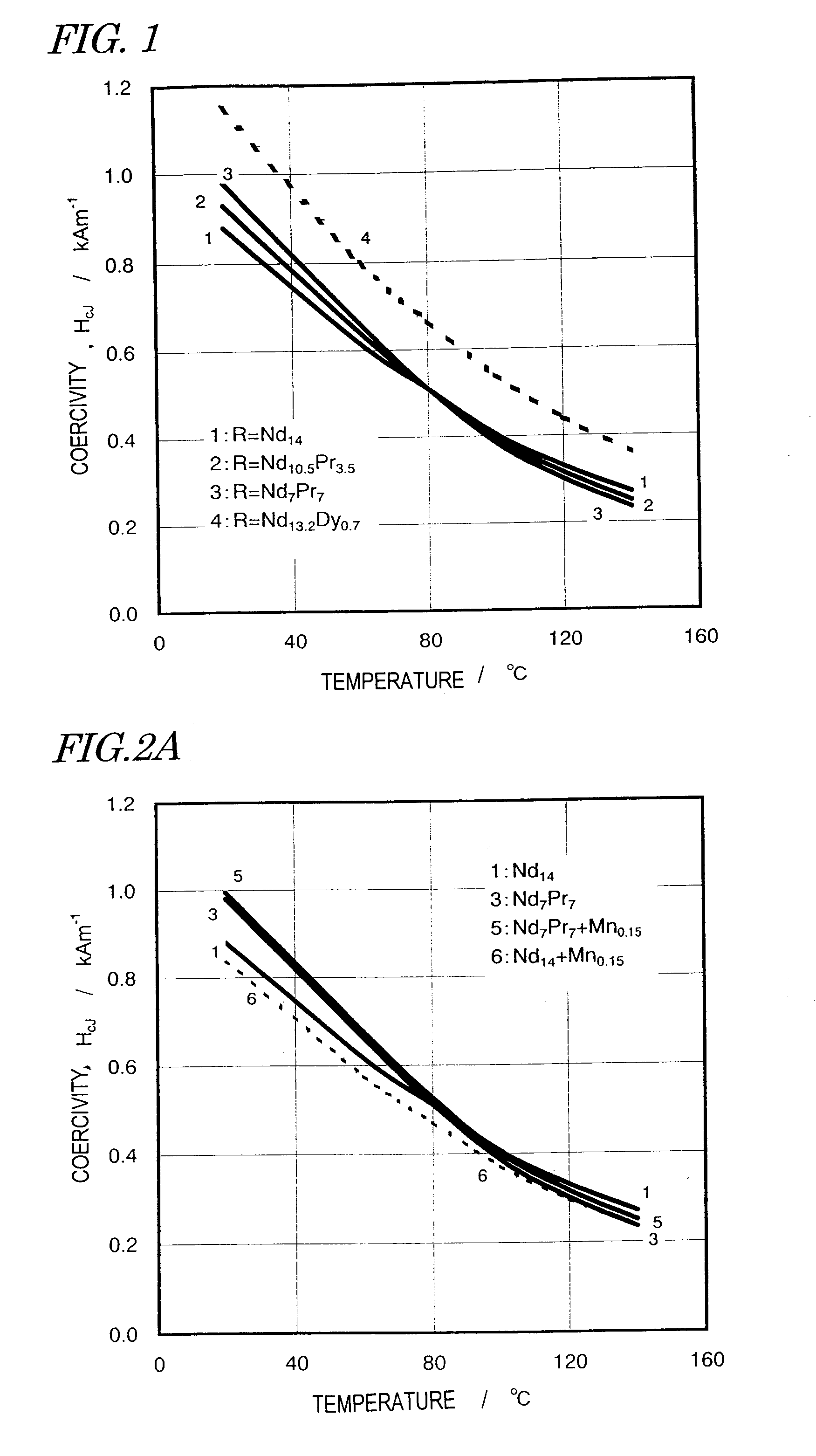
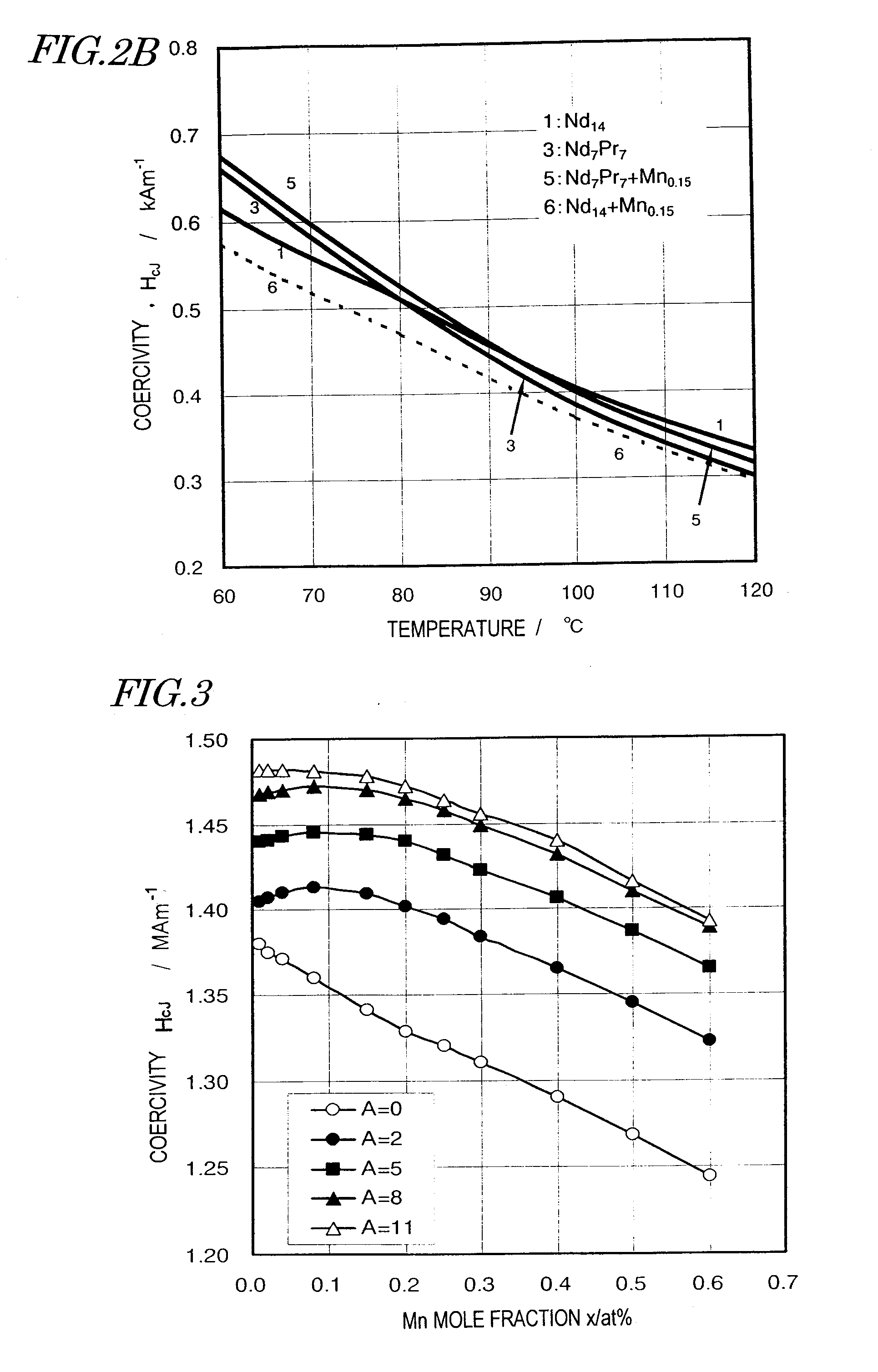
[0094]Magnets, of which the compositions were represented by Nd13.5-APrADy1.0Febal.Co2.0Al0.5Cu0.1MnxB6.0 (where subscripts are atomic percentages), had their coercivity measured at room temperature with the mole fraction A of Pr set to be 0, 2, 5, 8 and 11 (at %) and with the mole fraction x of Mn varied. The results are shown in FIG. 3. The magnets of this Example 2 were produced by the same method as that adopted for Example 1.

[0095]As can be seen from FIG. 3, in a situation where A=0, as Mn was added, the coercivity decreased monotonically. On the other hand, if a portion of the rare-earth element was replaced with Pr, the coercivity rather increased as long as the amount of Mn added fell within a particular range.

[0096]However, in a situation where the mole fraction A of Pr was 11 at %, the coercivity did not increase appreciably even if Mn was added.

example 3

[0097]Sintered magnets, of which the compositions were represented by Nd11.5Pr1.0Dy1.2Febal.Cu0.1MnxB6.0 (where subscripts are atomic percentages), were made with the mole fraction x varied and had their magnetic properties measured. The results are shown in the following Table 2:

TABLE 2Mole fractionDensityMagnetic propertiesNo.x of Mn (at %)ρ / MGm−3Jr / THCJ / kAm−1Hk / HCJ210.017.341.33710260.926220.027.491.36811220.971230.057.511.37211550.989240.107.541.37611340.987250.157.531.37211190.987260.207.541.36811050.988270.257.541.36310910.987280.307.531.36010740.988290.407.541.35110400.985300.507.541.34310080.988310.607.541.3359810.983320.807.531.3169080.978

[0098]The same manufacturing process as that adopted for Example 1 was also carried out. Every magnet with any of these compositions was sintered at 1,020° C. for two hours. The magnetic properties were evaluated by calculating Hk as an index and figuring out Hk / HcJ as an index to loop squareness. In this case, Hk represents a value of a d...


PUM

PropertyMeasurementUnit
Curie temperatureaaaaaaaaaa
thermal resistanceaaaaaaaaaa
temperaturesaaaaaaaaaa

Abstract

An R-T-B based sintered magnet according to the present invention comprises: 12 at % to 15 at % of a rare-earth element R; at % to 8.0 at % of boron B; 0.02 at % to 0.2 at % of Mn; and a transition metal T as the balance. The rare-earth element R is at least one element selected from the rare-earth elements, including Y (yttrium), and includes 0.2 at % to 8 at % of Pr. And the transition element T includes Fe as its main element.

Description

[0001]This application is a continuation application of U.S. application Ser. No. 12 / 132,738 filed on Jun. 4, 2008, which is a continuation of International Application No. PCT / JP2007 / 059384, with an international filing date of May 2, 2007.BACKGROUND OF THE INVENTION[0002]1. Field of the Invention[0003]The present invention relates to an R-T-B (rare-earth-iron-boron) based sintered magnet.[0004]2. Description of the Related Art[0005]R-T-B based sintered magnets have so good magnetic properties as to find a wide variety of applications including various types of motors and actuators and are now one of indispensable materials for the electronics industry. Also, their applications have been appreciably broadened to keep up with the recent trend toward energy saving.[0006]Lately, however, those motors and actuators are more and more often required to exhibit much higher performance than conventional ones in their rapidly expanding applications including motors for driving, or generatin...

Claims


Application Information

Patent Timeline
Patent Type & Authority Applications(United States)
IPC IPC(8): C22C38/04C22C38/10C22C38/12C22C38/00
CPCC22C38/005H01F1/0577C22C38/06C22C38/04C22C38/10
Inventor TOMIZAWA, HIROYUKI
Owner HITACHI METALS LTD
Why Eureka
Try Eureka