High switching speed digital faraday rotator device and optical switches containing the same

a rotator device and high switching speed technology, applied in the direction of optical radiation measurement, instruments, polarising elements, etc., can solve the problems of high switching speed and long-term operation reliability of optical switches, limited switching speed, and easy material fatigue of moving parts

Inactive Publication Date: 2003-07-15
SUI ZHIFENG
View PDF5 Cites 42 Cited by
  • Summary
  • Abstract
  • Description
  • Claims
  • Application Information

AI Technical Summary

Benefits of technology

It is the object of the present invention to provide a compact, non-mechanical, non-blocking and high speed optical switch.
A preferred embodiment of this invention discloses a basic digital Faraday rotator device that comprises (a) a semi-hard or hard magneto-optic iron garnet-based crystal having bi-stable magnetization states at zero external magnetic field. (b) a wire winding around the crystal for changing the magnetization states by pulsed current having both fast rise time and short duration. (c) a circuit generating the required current pulses with both polarities. After a driving current pulse excitation to set the magnetization direction, the high coercive force and high remnant squareness in the garnet-based crystal will maintain the saturation magnetization state in the crystal without the need of any external current or magnetic field to sustain the remnant state.
The charging and discharging circuit through a capacitor controls the polarity of the driving current pulses and that controls the states of magnetization and polarization. The configuration significantly simplifies the circuit design. The current pulse is programmable and can also be controlled remotely.

Problems solved by technology

As more fiber optic network systems are installed for carrying out optical signal transmissions, a technical challenge is still faced by those of ordinary skill to provide optical switches with high switching speed and long term operation reliability.
Due to the need to mechanically move the optical element(s), switching speed is very limited, typically in millisecond range.
Furthermore, the moving part is susceptible to material fatigue and worn out of linkages, particularly to these components connected to the moving parts.
Long-term reliability becomes a major problem for design, operation, and maintenance of the optical network signal transmission systems as that discussed by P. G. Hale and R. Kompfner, in a paper "Mechanical Optical-Fiber Switch," Electron. Lett. 12, 388 (1976).
The drawback of this scheme is that it requires a continuous high current source to maintain the magnetization state in the Faraday rotator, resulting in high power consumption.
However, the material properties of the semi-hard magnet has to be carefully optimized so that it is not too hard to drive, yet hard enough to sustain the required remnant state.
These devices however require complicated electromagnet design.
Additionally, the devices are more expensive because sophisticated magnet with optimized material property has to be used.

Method used


Image

  • High switching speed digital faraday rotator device and optical switches containing the same
  • High switching speed digital faraday rotator device and optical switches containing the same
  • High switching speed digital faraday rotator device and optical switches containing the same

Examples


Embodiment Construction

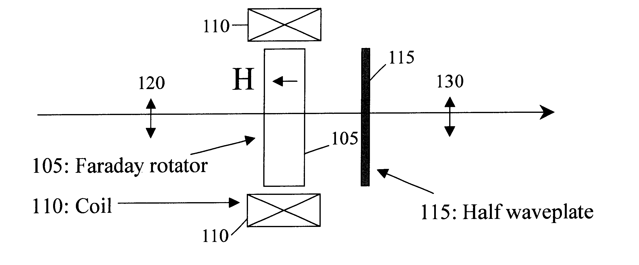
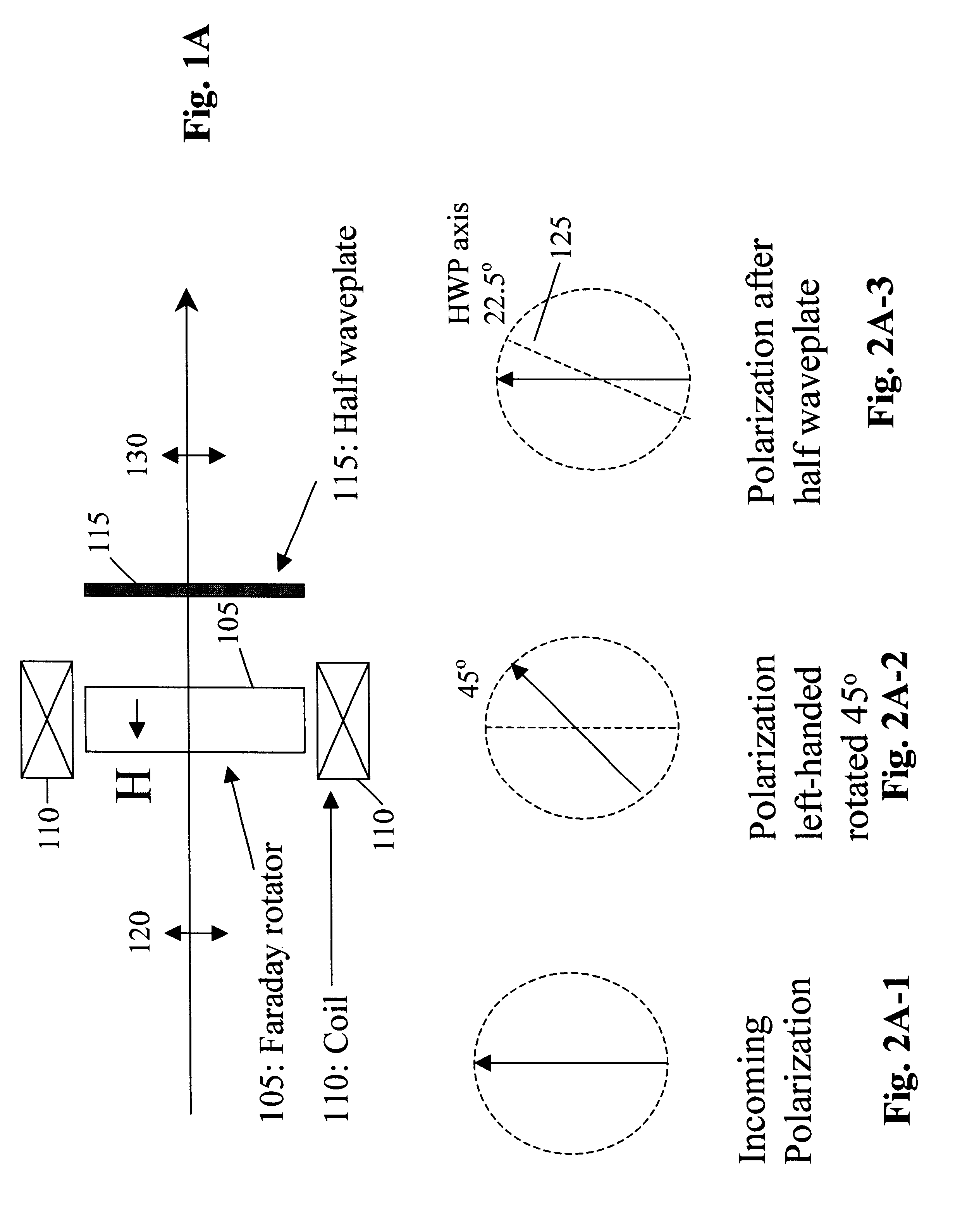
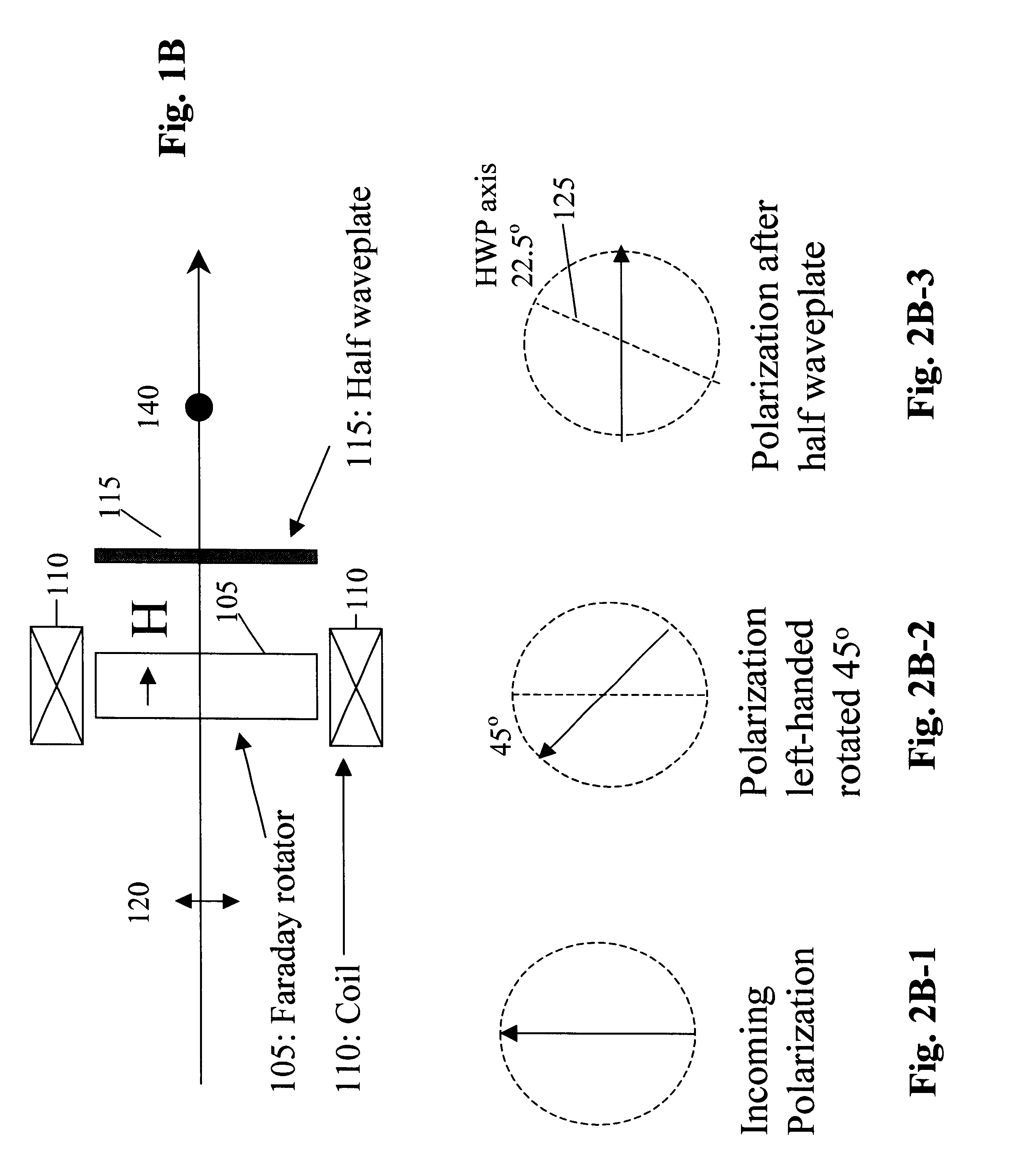
Referring to FIGS. 1A and 1B, for the basic digital Faraday rotator device of this invention. The Faraday rotator 100 is composed of a semi-hard or hard magneto-optic garnet-based crystal 105 having bi- stable magnetization states at zero external magnetic field and a wire winding 110 around the crystal for changing the magnetization states. An example of the garnet crystal is the well-known Bi- and Al-substituted iron garnet as published in the article "Magnetic and Magneto-optic Properties of Bismuth- and Aluminum-substituted Iron Garnet Films", Journal of Applied Physics, Vol. 55, No.4, pp: 1052-1061, Feb., 1984. Referring to FIGS. 2A and 2B for a function of controlling the polarization states. As shown in FIGS. 2A-1 and FIG. 2A-2, at one specific magnetization state, the Faraday rotator 100 rotates the polarization 120 of the incoming light by forty-five degrees clockwise. After passing through a half wave-plate (HWP) 115 with its optical axis 125 at 22.5 degrees as shown in FI...


PUM

PropertyMeasurementUnit
hysteresis coercivityaaaaaaaaaa
peak currentaaaaaaaaaa
polarization angleaaaaaaaaaa

Abstract

In all-optical networks, high speed optical switching and routing becomes one of the most important issues for interconnecting the transport network layers. This invention describes novel polarization-independent high speed optical switches using a digital Faraday rotator, which can also be used for various other optical switching devices. The basic digital Faraday rotator device is composed of (a) a semi-hard or hard iron garnet based magneto-optic crystal having bi-stable magnetization states at zero external magnetic field. (b) a wire winding around the crystal for changing the magnetization states by pulsed current having both fast rise time and short duration. (c) a circuit generating the required current pulses with both polarities. After a driving current pulse excitation to set the magnetization direction, the high coercive force and high remnant squareness in the garnet-based crystal will maintain the saturation magnetization state in the crystal without the need of any external current or magnetic field to sustain the remnant state. The apparatus and the method disclosed in this invention effectively reduces the overall power consumption. By using this digital Faraday rotator device, the polarization independent 1x2 and 2x2 optical switches are designed and fabricated.

Description

1. Field of the InventionThe invention relates generally to method and apparatus for optical signal transmission. More particularly, this invention relates to bi-stable polarization control method and apparatus for configuring high-speed optical switches.2. Descriptions of the Prior ArtAs more fiber optic network systems are installed for carrying out optical signal transmissions, a technical challenge is still faced by those of ordinary skill to provide optical switches with high switching speed and long term operation reliability. An optical network system typically incorporates one or more switches to direct the optical paths for transmitting the optical signal to the desired destinations. In addition to the general requirements of low insertion loss, small cross talk, high extinction ratio, low polarization-dependent loss, etc., increasingly there is a demand for optical switches that have a high switching speed and good long-term reliability. The switching speed and reliability...

Claims


Application Information

Patent Timeline
Patent Type & Authority Patents(United States)
IPC IPC(8): G02F1/09G02F1/01G02F1/31G02F1/29
CPCG02F1/09G02F1/31G02F1/092
Inventor SUI, ZHIFENG
Owner SUI ZHIFENG
Why Eureka
Try Eureka