Photoacoustic gas sensor utilizing diffusion

a technology of photoacoustic gas and sensor, applied in the field of photoacoustic gas sensors utilizing diffusion, can solve the problems of generating photoacoustic signals, affecting the output signal of such photoacoustic detectors, and microphones b>15/b> can absorb parts, etc., and achieve the effect of improving the response time of the sensor and faster initial rise time to t50

Active Publication Date: 2006-09-12
MSA TECH
View PDF10 Cites 9 Cited by
  • Summary
  • Abstract
  • Description
  • Claims
  • Application Information

AI Technical Summary

Benefits of technology

[0008]Generally, the present invention provides a method and device for controlling the diffusion of the analyte gas within a diffusive photoacoustic gas sensor to improve the response time of the sensor. The photoacoustic gas sensor or detector of the present invention comprises a sensing volume and an acoustic pressure sensor volume. The sensing volume is in fluid connection with the environment through an acoustic pressure attenuating element such that the analyte gas can diffuse into the sensing volume through the acoustic pressure attenuating element. The acoustic pressure sensor volume is in fluid connection with the sensing volume such that the transfer or transmission of the photoacoustic pressure signal therebetween is not adversely affected or significantly limited while at the same time the rate of analyte gas diffusion into the acoustic pressure sensor volume is controlled; for example, restricted, hindered, slowed and / or blocked, such that it is less than the rate of analyte gas diffusion from the environment into the sensing volume. As a result, the initial response time of the photoacoustic sensor, both rising and falling, will be based only on the time for the analyte gas to diffuse into or out of the sensing volume, and not on the time for the analyte gas to diffuse into or out of the combined volume of the sensing volume and the acoustic pressure sensor volume. Thus the response time of the photoacoustic sensor is independent of the size of the acoustic pressure sensor volume relative to the size of the sensing volume. Preferably, a faster initial rise time to T50 and T90 can be achieved by restricting, limiting, hindering or controlling the analyte diffusion to the acoustic pressure sensor volume.
[0009]In a preferred embodiment of the present invention, the analyte gas diffusion between the sensing volume and the acoustic pressure sensor volume occurs in close proximity to and preferably adjacent to the source of the analyte gas diffusion from the environment into the sensing volume. Preferably, the connection between the sensing volume and the acoustic pressure sensor volume is located in or near a corner or edge of the sensing volume adjacent to the source of the analyte gas diffusion from the environment into the sensing volume so that the small amount of gas diffusion that does occur through the connection has the least photoacoustic effect.

Problems solved by technology

Locating the microphone 15 in the wall of the sensing volume 16, however, has the disadvantage that the microphone 15 can absorb part of the light from the light source 17 incident upon the sensing chamber 16 and generate a photoacoustic signal in the absence of any analyte gas.
The output signal of such a photoacoustic detector, however, is susceptible to noise created by interference from outside sources of sound / pressure waves, such as wind, building ventilation systems, and other vibration and acoustic phenomena.
Introduction of such an acoustic pressure attenuating element to reduce noise, however, typically results in a corresponding loss of responsiveness to changing signal levels.
However, if a diffusion photoacoustic detector is used, the initial response time is typically limited by the diffusion rate of the analyte gas through the acoustic pressure attenuating element 20.

Method used


Image

  • Photoacoustic gas sensor utilizing diffusion
  • Photoacoustic gas sensor utilizing diffusion
  • Photoacoustic gas sensor utilizing diffusion

Examples


Embodiment Construction

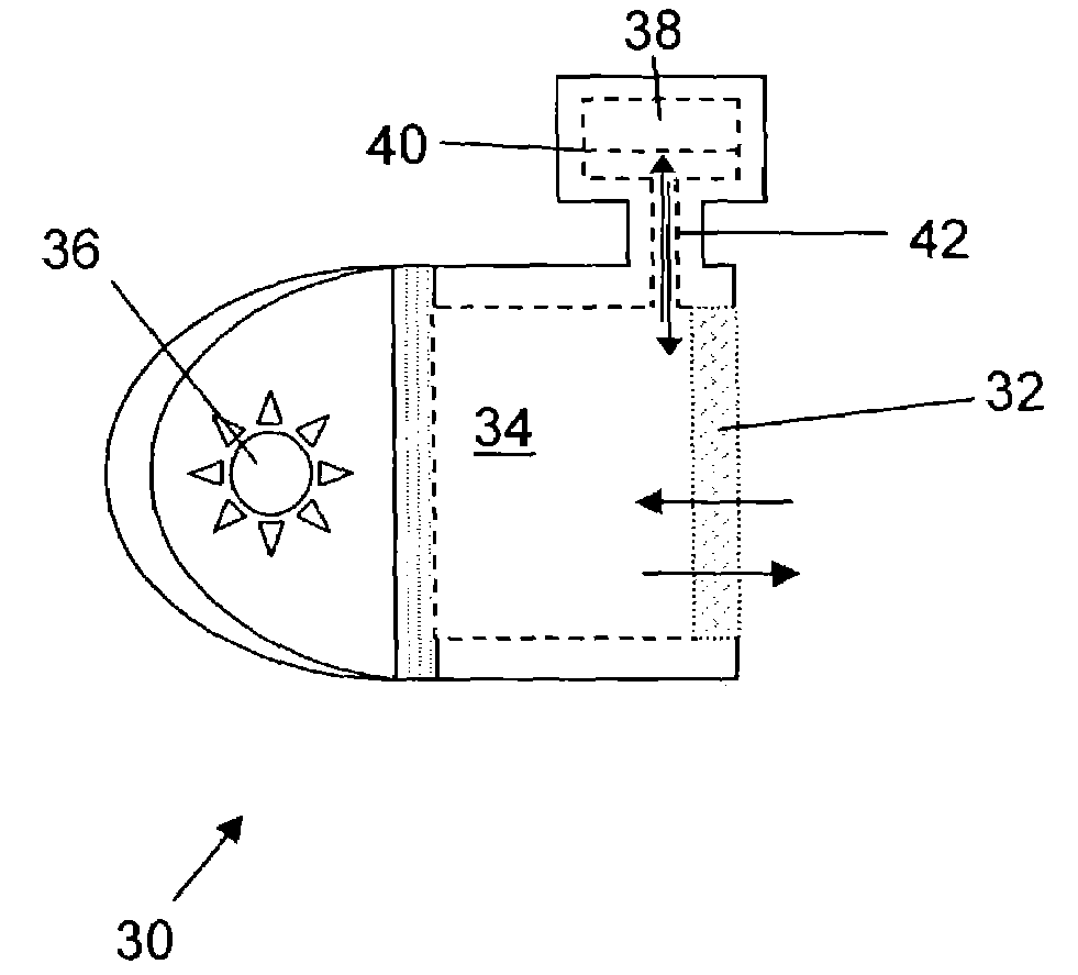
[0018]A preferred embodiment of a diffusive photoacoustic gas detector 30 of the present invention is illustrated in FIG. 4. Reference is made to U.S. Pat. No. 4,740,086, the disclosure of which is incorporated by reference as if fully set forth herein, for the principles of operation and construction of a photoacoustic sensor / detector. In the embodiment of FIG. 4, an acoustically attenuating element 32 that is continuously permeable to an analyte gas makes up a portion of the wall of the sensing volume 34. As is known in the art, the acoustically attenuating element 32 acts to reduce external sources of sound / pressure waves from entering the sensing volume 34 and acts to ensure that the resulting photoacoustic pressure signal is not weakened by the escape of such signal from the sensing volume 34 while offering only minimal resistance to the diffusion of the analyte gas into the sensing volume 34. Preferably, the optical energy from the light source 36 enters through another portio...


PUM

PropertyMeasurementUnit
lengthaaaaaaaaaa
diameteraaaaaaaaaa
diameteraaaaaaaaaa

Abstract

The present invention relates to a photoacoustic gas sensor utilizing diffusion having a sensing volume and an acoustic pressure sensor volume containing an acoustic pressure sensor such that the fluid connection between the sensing volume and the acoustic pressure sensor volume restricts the flow of analyte gas therethrough but does not restrict the transmission of the photoacoustic signal therethrough.

Description

FIELD OF INVENTION[0001]The present invention relates generally to photoacoustic gas sensors utilizing diffusion and more particularly, to devices and methods for reducing the initial response time and increasing the signal-to-noise ratios in photoacoustic gas sensors utilizing diffusion.BACK OF THE INVENTION[0002]The use of gas sensors to detect the concentration level of a gaseous analyte (i.e., species of interest) using the photoacoustic effect is well known. For example, U.S. Pat. No. 4,740,086 teaches the use of a photoacoustic gas sensor to convert the optical energy of an amplitude modulated light source into acoustic energy when the light excites the gaseous analyte. Sound / pressure waves of an intensity corresponding to the concentration level of the analyte gas within the sensing volume or sensing chamber are generated as the optical energy of the light incident upon the sensing chamber is, upon absorption by the analyte gas, converted into raised energy levels of the anal...

Claims


Application Information

Patent Timeline
Patent Type & Authority Patents(United States)
IPC IPC(8): G01N21/00G01N21/03G01N21/17
CPCG01N21/1702G01N2021/1704G01N2021/0346
Inventor UBER, ROBERT E.
Owner MSA TECH
Why Eureka
Try Eureka