Air conditioner or compressor for refrigerator driven by permanent magnet synchronous motor

A permanent magnet synchronous and refrigerator technology, applied to synchronous motors with static armatures and rotating magnets, magnetic circuit rotating parts, magnetic circuit static parts, etc., can solve the problem of being susceptible to demagnetization and low winding efficiency , the complex winding process and other problems, to reduce costs, improve productivity, improve the effect of anti-demagnetization

Inactive Publication Date: 2009-09-16
PANASONIC CORP
View PDF8 Cites 1 Cited by
  • Summary
  • Abstract
  • Description
  • Claims
  • Application Information

AI Technical Summary

Problems solved by technology

[0004] However, the distributed winding method has problems in that the winding process is complicated and the winding efficiency is low, and the rare earth magnet is expensive, and the sensor for detecting the rotation phase is also expensive, so the cost is high
[0010] So far, although there have been many motors with concentrated winding methods, when the pole piece spacing is very narrow and the polarities of adjacent pole pieces are opposite, the permanent magnet is easily demagnetized. If a permanent magnet with a small coercive force such as ferrite is used Magnets, the ability to resist demagnetization becomes weak
Especially in the case of sensorless driving, there is a high possibility of being subjected to a reverse magnetic field at the time of starting and out of step, and there is a problem that it is extremely easy to demagnetize

Method used


Image

  • Air conditioner or compressor for refrigerator driven by permanent magnet synchronous motor
  • Air conditioner or compressor for refrigerator driven by permanent magnet synchronous motor
  • Air conditioner or compressor for refrigerator driven by permanent magnet synchronous motor

Examples


Embodiment 1

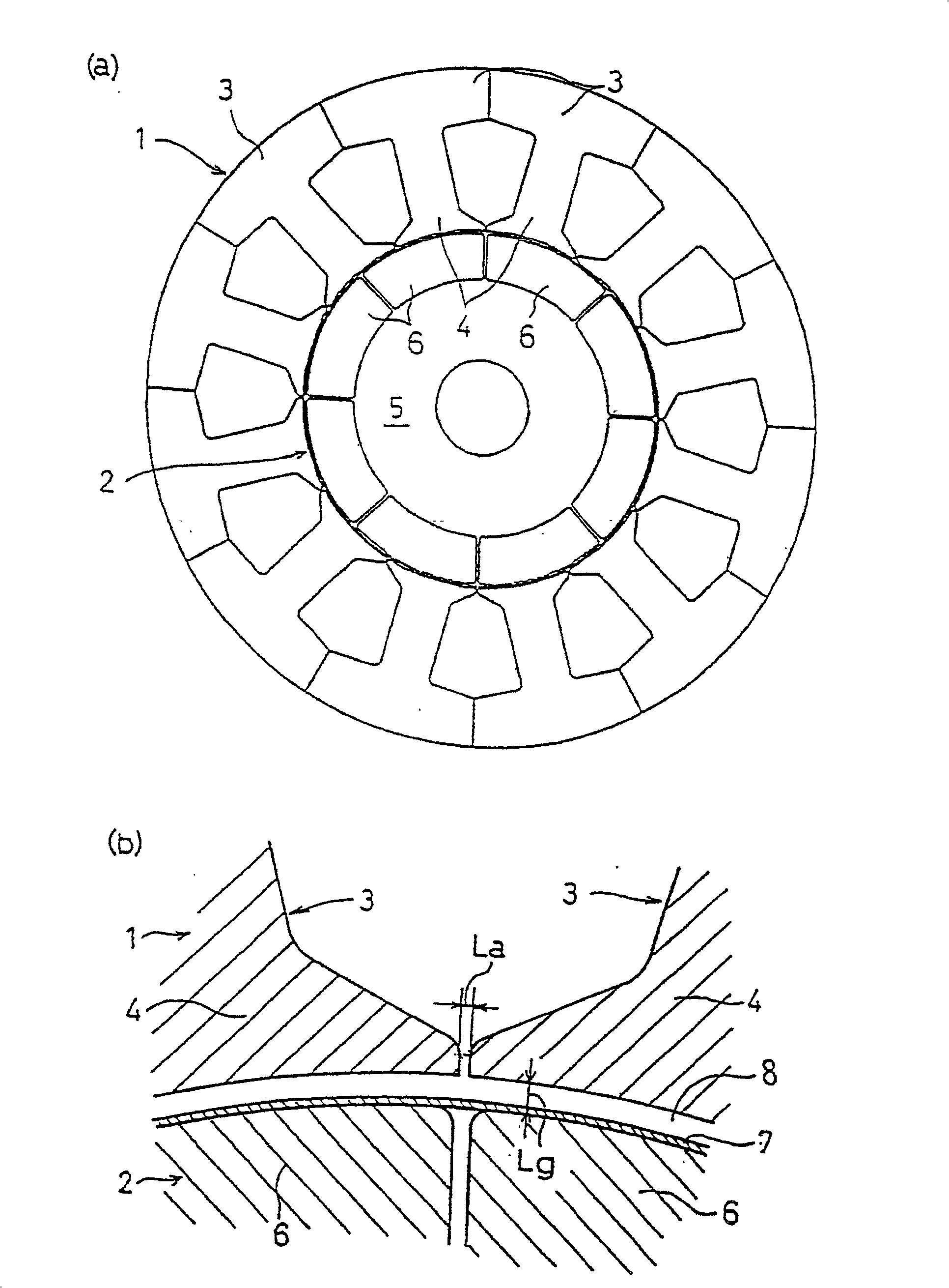
[0038] Refer to the following figure 1 , figure 2 , to illustrate Embodiment 1 of a permanent magnet synchronous motor, which is a motor for driving a compressor for an air conditioner or a refrigerator of the present invention.

[0039] exist figure 1Among them, 1 is the stator, and 2 is the rotor. The stator 1 is composed of split iron cores 3 corresponding to the number of slots, and windings (not shown) are independently wound on the pole shoes 4 of each split iron core 3, and the concentrated winding method is adopted. . The rotor 2 is formed by fixing a permanent magnet 6 composed of a plurality of ferrite magnets to the outer periphery of a rotor core 5 formed by laminating silicon steel sheets, and a rotating shaft (not shown) penetrating and fixed to the axial center is supported by a bearing. Can be turned freely. The outer circumference of the rotor 2 is covered with a thin plate cylinder 7 made of stainless steel, or a reinforcing belt is wound to ensure the...

Embodiment 2

[0045] Then refer to image 3 , Figure 4 , to describe Embodiment 2 of the permanent magnet synchronous motor for driving the compressor of the present invention. In addition, the description of the same constituent elements as those of the first embodiment will be omitted, and only the points of difference will be described. The same applies to the following examples.

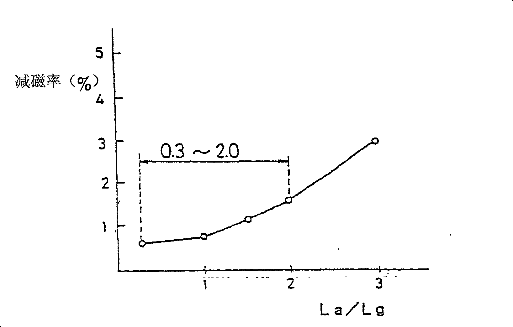
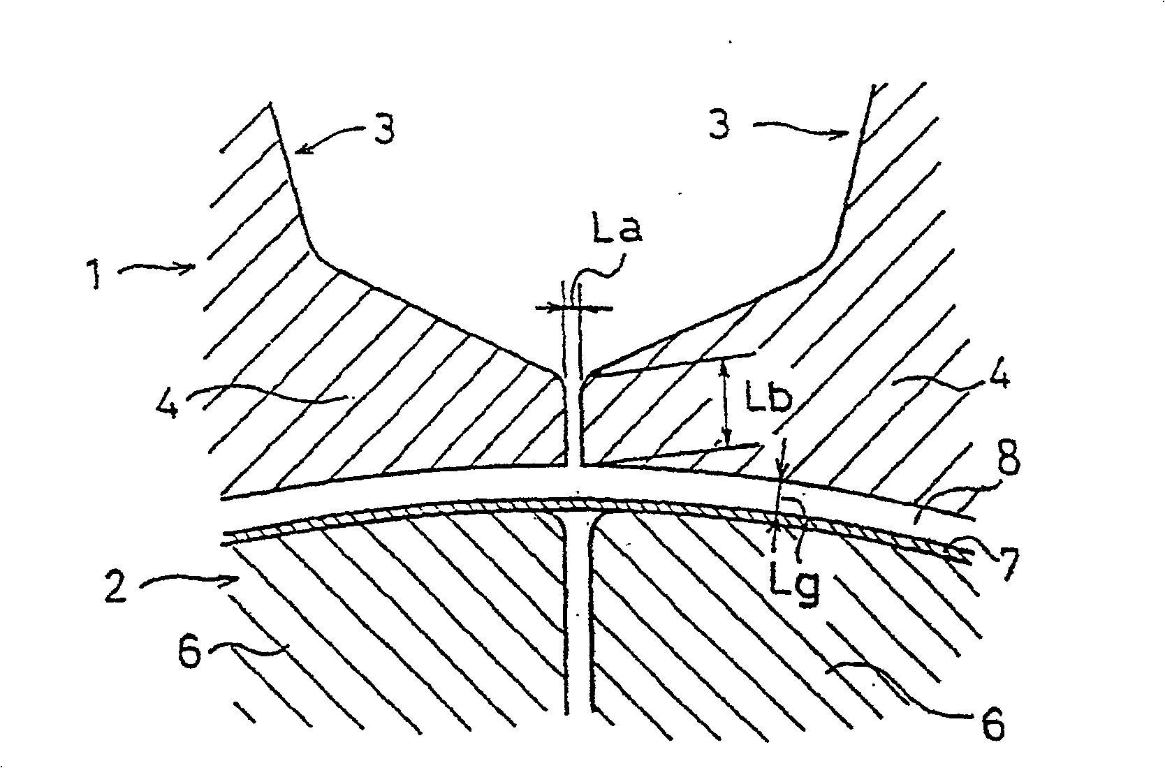
[0046] exist image 3 In the setting, the distance between the pole shoes 4 and 4 of the stator 1 is La, the end thickness of the pole shoes 4 of the stator 1 is Lb, and the size of the air gap 8 between the stator 1 and the rotor 2 is Lg, then it is set as 0.3Lg

[0047] In this way, since the thickness Lb of the end of the pole piece 4 of the stator 1 is larger than twice the air gap Lg between the stator 1 and the rotor 2 on the basis of the above-mentioned embodiment 1, the magnetic flux leakage can be further suppressed. By entering the rotor side, the ability to resist demagne...

Embodiment 3

[0051] Then refer to Figure 5 , Embodiment 3 of the permanent magnet synchronous motor for driving the compressor of the present invention will be described.

[0052] exist Figure 5 in the above image 3 On the basis of the structure of the shown embodiment 2, a cutout portion 9 (the end of the pole piece 4 and the rotor 2 is provided) on the side of the rotor 2 side at the opposite ends of the stator 1 adjacent to the pole pieces 4, 4. The interval between is represented by Lc).

[0053] The cutout portion 9 may be provided only at one end of the pole piece 4 of the stator 1 , that is, the end on the lower side in the rotation direction of the rotor 2 among the opposite ends of the adjacent pole pieces 4 , 4 .

[0054] By providing the cutout portion 9 in this way, the air gap at the end of the pole piece 4 can be enlarged, and the demagnetizing flux can be restrained from entering the rotor side, so that the same effect can be obtained.

[0055] Furthermore, in this em...


PUM


Abstract

An air conditioner or a refrigerator compressor is driven by a permanent magnet synchronous motor with a stator of a concentrated winding mode, the interval between the pole pieces of the stator (1) is La, the stator (1) and the rotor (2 ) is Lg, so that 0.3Lg<La≤2.0Lg, or, assuming that the pole shoe end thickness of the permanent stator (1) is Lb, the air gap between the stator (1) and the rotor (2) is Lg , and make 2Lg<Lb<5Lg. In addition, the outer peripheries of both circumferential end portions of the permanent magnets (6) provided on the outer peripheral portion of the rotor (2) may be formed in a concave shape that is recessed radially inward from the outer periphery of the rotor. In this way, it is difficult for the demagnetization field to act on the permanent magnet (6), thereby improving the demagnetization resistance of the permanent magnet (6).

Description

[0001] This application is a divisional application with the application number 02105150x, the filing date being September 7, 1998, and the name being "compressor for air conditioner or refrigerator driven by permanent magnet synchronous motor". technical field [0002] The present invention relates to a compressor for an air conditioner or a refrigerator, which is driven by a permanent magnet synchronous motor whose rotor is provided with a permanent magnet for generating a magnetic field, and in particular to an air conditioner driven by a permanent magnet synchronous motor with a stator having a concentrated winding method Or a compressor for a refrigerator. Background technique [0003] Compressors for air conditioners or refrigerators are generally driven by permanent magnet synchronous motors. In general, high-power permanent magnet synchronous motors increase the number of teeth of the stator and adopt a distributed winding method to make the synthetic magnetomotive f...

Claims


Application Information

Patent Timeline
Patent Type & Authority Patents(China)
IPC IPC(8): H02K21/16H02K1/14H02K1/27H02K1/06H02K1/16H02K1/18
Inventor 村上浩本田幸夫横手静浅野能成和田幸利广濑秀雄松下泰明
Owner PANASONIC CORP
Why Eureka
Try Eureka