Electric motor with embedded permanent magnet, and refrigerating air conditioning equipment equipped with same

a technology of permanent magnets and electric motors, which is applied in the direction of magnetic circuits characterised by magnetic materials, magnetic circuit shapes/forms/construction, magnetic circuit rotating parts, etc., can solve the problems of increasing the risk of demagnetization of electric motors used in a higher temperature atmosphere, increasing the risk of procurement and increasing the price, and achieving the effect of suppressing the magnet demagnetization

Active Publication Date: 2018-03-27
MITSUBISHI ELECTRIC CORP
View PDF34 Cites 0 Cited by
  • Summary
  • Abstract
  • Description
  • Claims
  • Application Information

AI Technical Summary

Benefits of technology

[0017]According to one embodiment of the present invention, it is possible to suppress the demagnetization of the magnet in spite of including the flux barrier and the slit.

Problems solved by technology

Therefore, there is a problem in that, in the comparison at the same current, electric motors used in a higher temperature atmosphere are more liable to be demagnetized.
However, in recent years, the rarity value of the heavy rare-earth elements has increased, and hence the risks of the difficulty in procurement and the rise in prices are increasing.

Method used


Image

  • Electric motor with embedded permanent magnet, and refrigerating air conditioning equipment equipped with same
  • Electric motor with embedded permanent magnet, and refrigerating air conditioning equipment equipped with same
  • Electric motor with embedded permanent magnet, and refrigerating air conditioning equipment equipped with same

Examples


first embodiment

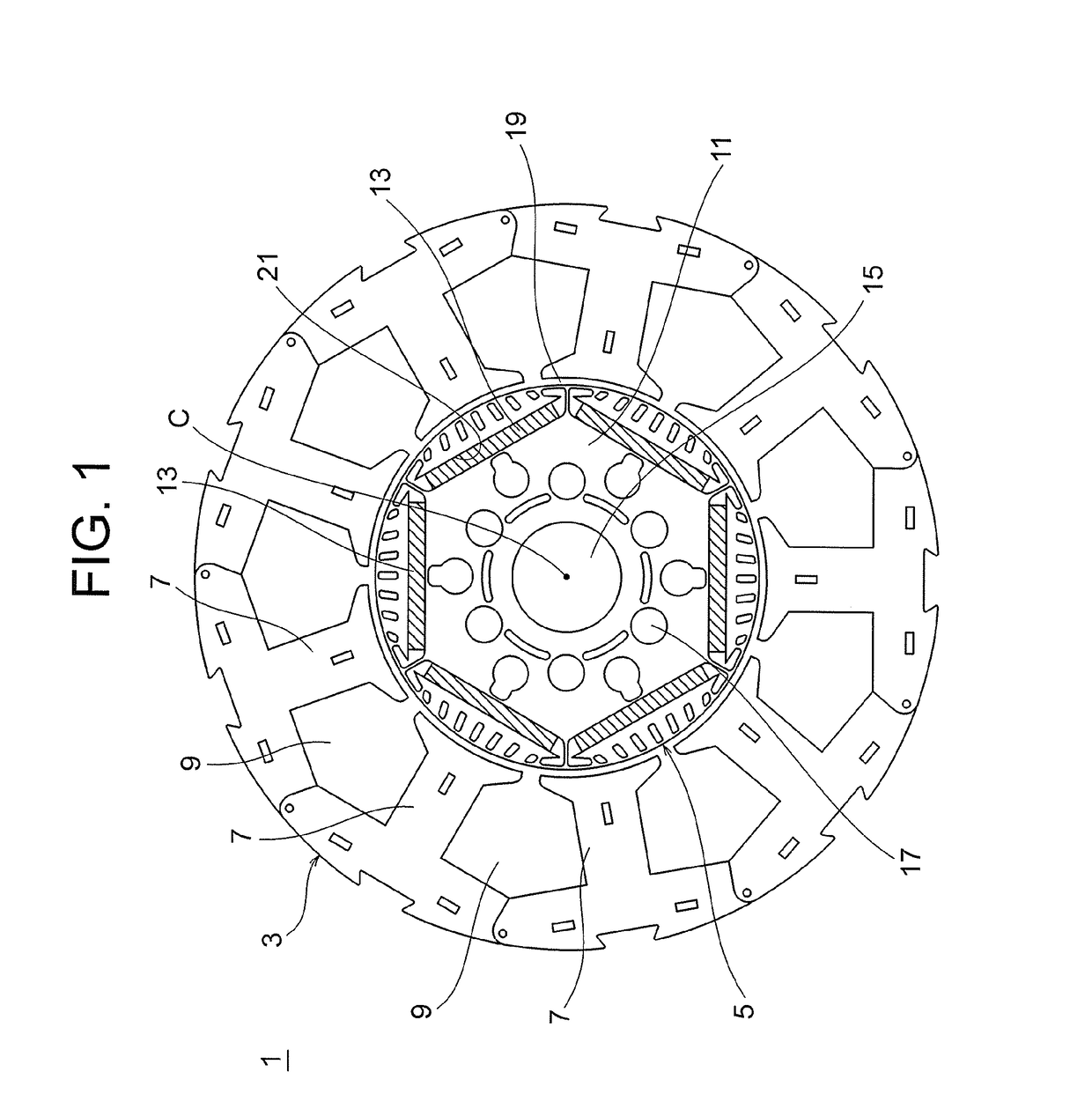
[0030]A permanent magnet embedded electric motor according to a first embodiment of the present invention is described. FIG. 1 is a view illustrating a permanent magnet embedded electric motor according to the first embodiment of the present invention.

[0031]As illustrated in FIG. 1, a permanent magnet embedded electric motor 1 includes a stator 3 and a rotor 5. The stator 3 includes a plurality of tooth portions 7 arranged equiangularly with an axial center C being the center. A well-known stator winding (not shown) is wound around each tooth portion 7. Further, slot portions 9 are formed between respective pairs of the corresponding tooth portions 7, and the slot portions 9 are also positioned equiangularly.

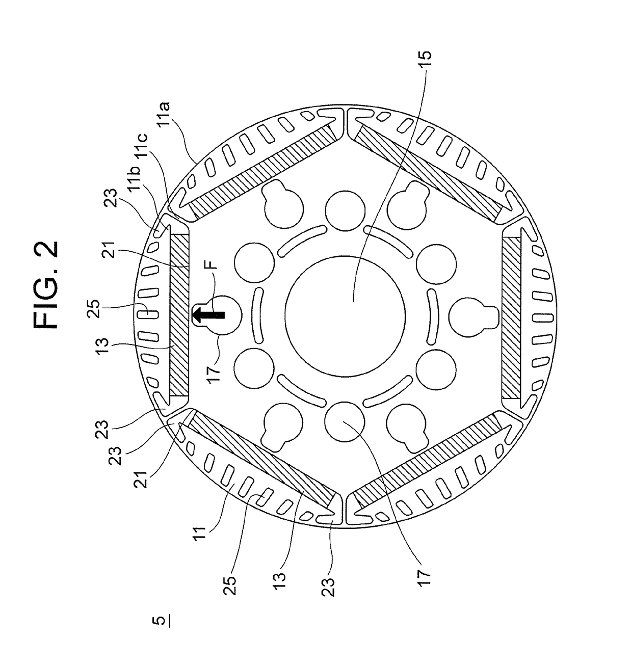
[0032]The rotor 5 includes at least a rotor core 11 and a plurality of permanent magnets 13. A shaft hole 15 is formed in a center portion including the axial center C of the rotor core 11. A well-known shaft (not shown) for transmitting rotation energy to the rotor core 11 is i...

second embodiment

[0065]A permanent magnet embedded electric motor according to a second embodiment of the present invention is described. FIGS. 10 and 11 are views illustrating the second embodiment of the present invention in the same manner as those of FIGS. 3 and 4, respectively. Note that, the second embodiment has the same configuration as that of the first embodiment except for portions described below.

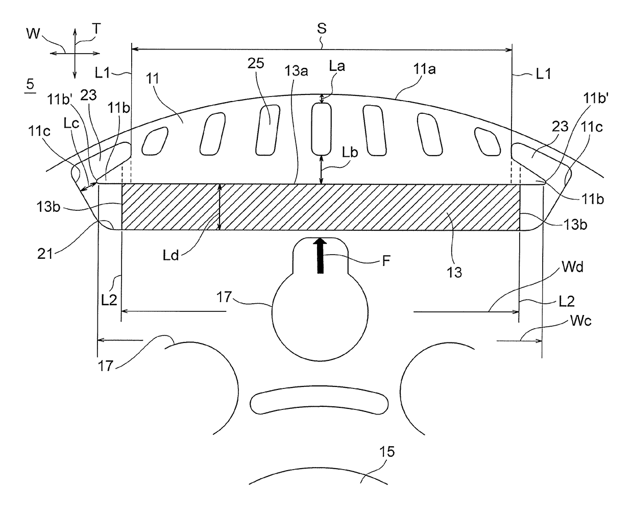
[0066]Also in a rotor 105 of the permanent magnet embedded electric motor according to the second embodiment, in the hole defining portion of the magnet insertion hole 21, an extended portion 111b is included in an area positioned further on the outer side of the circumferential direction with respect to the width-direction end surface 13b of each permanent magnet 13. The extended portion 111b projects toward the interpolar core portion 11c in the rotor core 11.

[0067]The extended portion 111b in the second embodiment is formed so as to gently project toward an inner diameter side with respect to...


PUM


Abstract

A permanent magnet embedded electric motor includes a slit and a flux barrier. A hole defining portion of a magnet insertion hole includes an extended portion. The extended portion projects toward an interpolar core portion in a rotor core in an area positioned further on an outer side of a circumferential direction with respect to a width-direction end surface of a permanent magnet. (Lb) is larger than (La), and (Lc) is smaller than (Ld), where the (La) represents a distance between the slit and the core outer peripheral surface; the (Lb) represents a distance between the slit and an outer peripheral-side surface of the permanent magnet; the (Lc) represents a shortest distance between the extended portion and the interpolar core portion; and the (Ld) represents a thickness of the permanent magnet.

Description

CROSS REFERENCE TO RELATED APPLICATIONS[0001]This application is a U.S. national stage application of International Patent Application No. PCT / JP2013 / 079218 filed on Oct. 29, 2013, and is based on International Patent Application No. PCT / JP2012 / 077981 filed on Oct. 30, 2012, the contents of which are incorporated herein by reference.TECHNICAL FIELD[0002]The present invention relates to a permanent magnet embedded electric motor and a refrigerating air-conditioning apparatus including the permanent magnet embedded electric motor.BACKGROUND ART[0003]An electric motor to be mounted on a compressor of a refrigerating air-conditioning apparatus is required to satisfy energy saving and low noise and to ensure the use in a high-temperature atmosphere at about 150° C. In general, a Nd—Fe—B based rare-earth magnet has a high residual flux density and hence is suitable for miniaturization and an increase inefficiency of the electric motor. However, as temperature increases, the magnetic coerc...

Claims


Application Information

Patent Timeline
Patent Type & Authority Patents(United States)
IPC IPC(8): H02K1/02F25B31/02H02K1/27
CPCH02K1/276H02K1/02F25B31/026H02K2213/03
Inventor NIGO, MASAHIROOKETANI, NAOHIROYABE, KOJIBABA, KAZUHIKO
Owner MITSUBISHI ELECTRIC CORP
Why Eureka
Try Eureka