Rotor, electric motor, compressor, air conditioner, and method for manufacturing electric motor

A rotor and gap technology, applied in the manufacture of motor generators, electrical components, air conditioning systems, etc., can solve the problems of motor efficiency decline and achieve the effect of suppressing demagnetization

Active Publication Date: 2019-01-04
MITSUBISHI ELECTRIC CORP
View PDF6 Cites 0 Cited by
  • Summary
  • Abstract
  • Description
  • Claims
  • Application Information

AI Technical Summary

Problems solved by technology

The efficiency of the motor decreases when the amount of magnetic flux from the permanent magnets decreases due to demagnetization

Method used


Image

  • Rotor, electric motor, compressor, air conditioner, and method for manufacturing electric motor
  • Rotor, electric motor, compressor, air conditioner, and method for manufacturing electric motor
  • Rotor, electric motor, compressor, air conditioner, and method for manufacturing electric motor

Examples


Embodiment approach 1

[0027] The motor 1 according to Embodiment 1 of the present invention will be described.

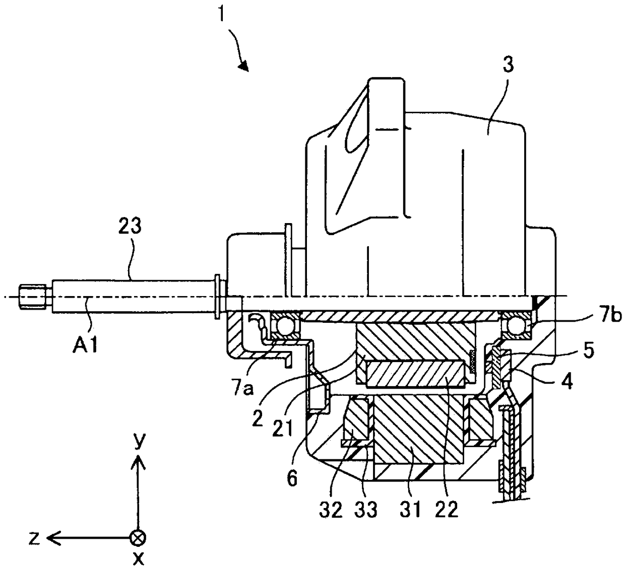
[0028] In the xyz rectangular coordinate system shown in each figure, the z-axis direction (z-axis) shows a direction parallel to the axis A1 (axis center) of the shaft 23 of the motor 1 (hereinafter referred to as "axis direction"), x The axial direction (x-axis) is a direction perpendicular to the z-axis direction (z-axis), and the y-axis direction is a direction perpendicular to both the z-axis direction and the x-axis direction.

[0029] figure 1 It is a cross-sectional view schematically showing the internal structure of the electric motor 1 according to Embodiment 1 of the present invention.

[0030] The motor 1 has a rotor 2, a stator 3, a substrate 4 on which electronic components such as a control circuit are mounted, a magnetic sensor 5 for detecting the rotational position of the rotor 2, a bracket 6, and bearings 7a and 7b. The motor 1 is, for example, an embedded permanen...

Deformed example 1

[0088] Figure 7 (a) is shown in Figure 6 (a) An enlarged view of the electromagnetic steel sheet 211 of the motor of Modification 1 of the region C4 shown by the dotted line, Figure 7 (b) is a 7b-7b sectional view of the electrical steel sheet 211 shown in (a), Figure 7 (c) is 7c-7c sectional drawing of the electrical steel sheet 211 shown in (a). With respect to the magnetic steel sheet 211 of the rotor 2 in Embodiment 1, Figure 7 z of the first end portion 211a, the second end portion 211b, the third end portion 211c, the fourth end portion 211d, and the fifth end portion 211e of the electrical steel sheet 211 in Modification 1 shown in (a) to (c). The position in the axial direction is different, and the other points are the same as those of Embodiment 1.

[0089] That is, if Figure 7 As shown in (b) and (c), the first end portion 211a, the second end portion 211b, the third end portion 211c, the fourth end portion 211d, and the fifth end portion 211e can be set ...

Deformed example 2

[0092] Figure 8 (a) is an enlarged view showing the structure of a part of the electromagnetic steel sheet 311 in the motor of Modification 2. FIG. Figure 8 (b) is an enlarged view showing the structure of a part of the electromagnetic steel sheet 311 of the rotor core 321 on which the permanent magnets 22 are arranged. Figure 8 (a) and (b) shown in the region C5 and figure 2 The region C1 shown corresponds to that. Compared with the rotor core 21 (specifically, the electromagnetic steel plate 211) of the rotor 2 in Embodiment 1, the structure of the magnet insertion hole 312 of the rotor core 321 (specifically, the electromagnetic steel plate 311) is different, and it is different from the rotor core 321 in other respects. Core 21 is the same. The rotor core 321 can be applied to the rotor 2 of the electric motor 1 according to Embodiment 1 instead of the rotor core 21 .

[0093] The rotor core 321 is formed by laminating a plurality of thin electromagnetic steel shee...


PUM

PropertyMeasurementUnit
Thicknessaaaaaaaaaa
Thicknessaaaaaaaaaa

Abstract

A rotor (2) has a first permanent magnet (22a), a second permanent magnet (22b), and an electromagnetic steel sheet (211). The electromagnetic steel sheet (211) has a magnet inserting hole (212), a protrusion (213), a first end section (211a), a second end section (211b), a third end section (211c), and a fourth end section (211d). When the thickness of the electromagnetic steel sheet (211) is represented by t, an angle formed between the third end section (211c) and the fourth end section (211d) is represented by R, and a distance from an intersection point (P1) where a straight line (L1) including the first end section (211a), and a straight line (L3) including the third end section (211c) intersect each other, to an intersection point (P0) where a straight line (L3) including the thirdend section (211c), and a straight line (L4) including the fourth end section (211d) intersect each other, is represented by w, the rotor (2) satisfies formula t<=2*w*sin (R / 2)<=2*t.

Description

technical field [0001] The present invention relates to a rotor provided with permanent magnets. Background technique [0002] In a motor, when the amount of magnetic flux generated from the stator (magnetic flux toward the rotor) is large, the amount of magnetic flux from the permanent magnets arranged on the rotor decreases. In general, this phenomenon is called demagnetization (hereinafter also referred to as "the demagnetization characteristic of the permanent magnet deteriorates."). As the amount of magnetic flux from the permanent magnets decreases due to demagnetization, the efficiency of the motor decreases. Therefore, in order to suppress demagnetization, a rotor has been proposed in which a position through which magnetic flux from a stator passes is considered. For example, in the rotor of the permanent magnet type brushless DC motor described in Patent Document 1, gaps are formed between adjacent permanent magnets to suppress leakage of magnetic flux from the p...

Claims


Application Information

Patent Timeline
IPC IPC(8): H02K1/27
CPCF24F1/10H02K1/2766H02K15/03H02K15/12H02K2213/03F24F1/22H02K1/16H02K1/28
Inventor 矢部浩二藤末义和
Owner MITSUBISHI ELECTRIC CORP
Why Eureka
Try Eureka