
Liquid ejecting head and liquid ejecting apparatus

a liquid ejecting head and liquid ejecting technology, which is applied in the direction of printing and inking apparatus, etc., can solve the problems of inability to eject ink, and increase the fluid resistance of ink, so as to achieve the effect of suppressing the thickening of liquid

Active Publication Date: 2018-12-27
CANON KK
View PDF16 Cites 13 Cited by
  • Summary
  • Abstract
  • Description
  • Claims
  • Application Information

AI Technical Summary

Benefits of technology

The present invention is about a liquid ejecting head and a liquid ejecting apparatus that can prevent liquid from becoming thick near the area where liquid is ejected. This invention helps to keep the liquid flowing smoothly through the system and prevents blockages.

Problems solved by technology

In a case where such thickening of ink occurs, an ink ejection speed and an ink ejecting direction from the ejection port are changed and the landing accuracy of ink droplets may be possibly affected.
Particularly, in a case where pause time of not ejecting ink is long, the increase of the viscosity of ink is remarkable and the solid component of ink adheres to the vicinity of the ejection port, thereby increasing fluid resistance of ink and possibly inducing failure of ink ejection.
However, the present inventors have found out, as a result of the study, that the mere configuration of circulating ink as disclosed in Japanese Patent Laid-Open No. 2002-355973 may have a possibility of causing color unevenness on a printed image due to a change in concentration of a coloring material in ink.
Particularly, in a case where at least one of the following conditions is satisfied, that is, a case where the volume of an ink droplet to be ejected is small, a case where the print head has a high temperature, and a case where a solid component of ink is high, the concentration of the coloring material in ink has been changed, and thus the color unevenness on a printed image has likely been occurred.

Method used


Image

  • Liquid ejecting head and liquid ejecting apparatus
  • Liquid ejecting head and liquid ejecting apparatus
  • Liquid ejecting head and liquid ejecting apparatus

Examples


Embodiment Construction

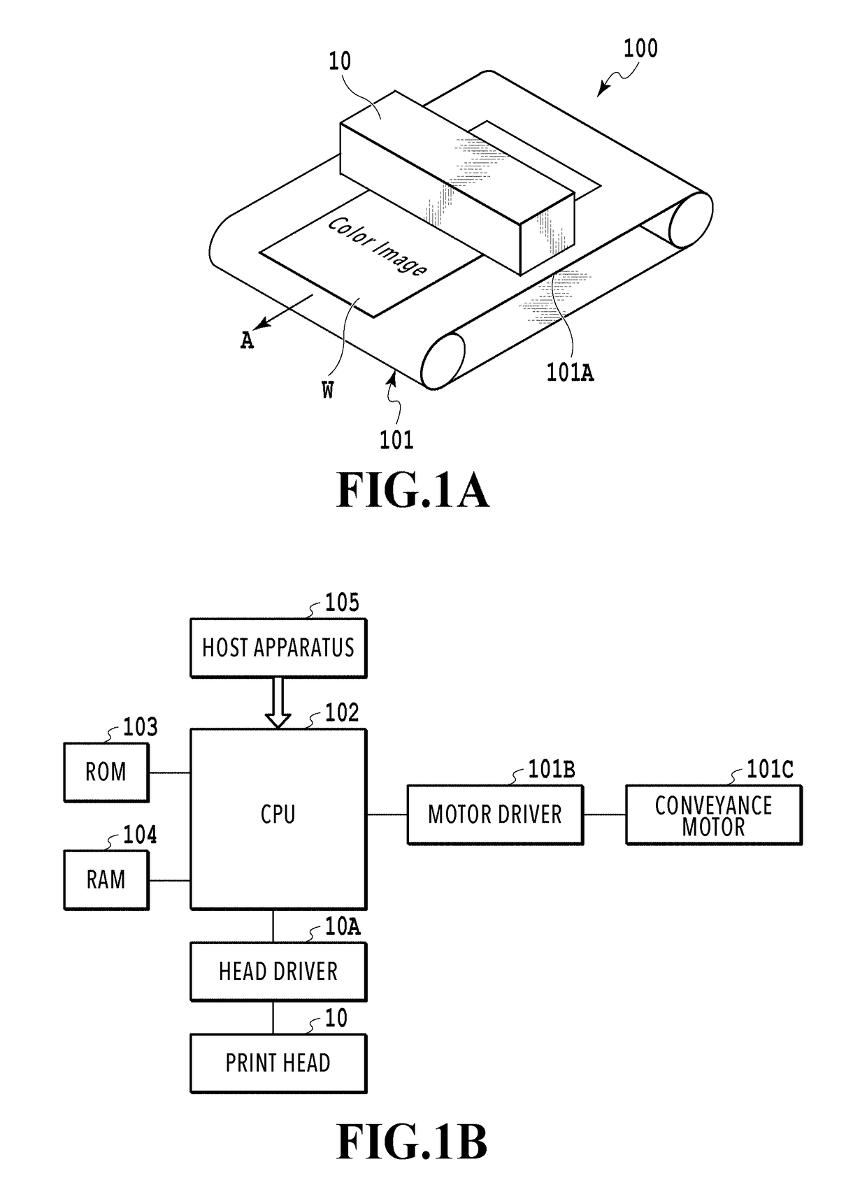
[0041]A liquid ejecting head and a liquid ejecting apparatus in the following embodiments are application examples as an inkjet print head which can eject liquid ink and an inkjet printing apparatus.

(Configuration of Printing Apparatus)

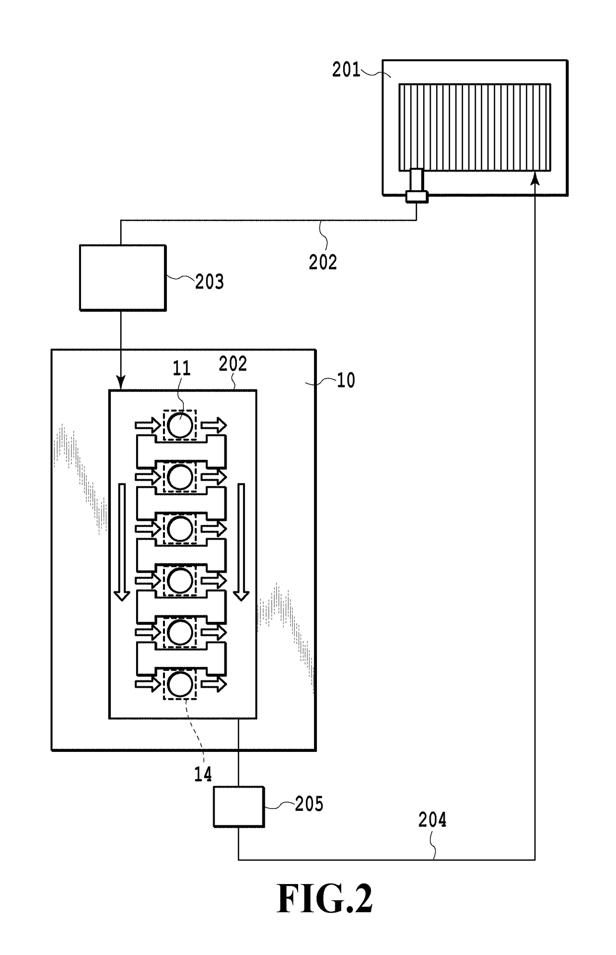
[0042]FIG. 1A is a schematic perspective view of major parts for illustrating a basic configuration of an inkjet printing apparatus (liquid ejecting apparatus) 100 applicable to the present invention. The printing apparatus 100 of this example is a printing apparatus of a so-called full line system, which includes a conveying unit 101 which conveys a print medium W in a conveying direction of an arrow A and an inkjet print head (liquid ejecting head) 10 capable of ejecting ink (liquid). The conveying unit 101 of this example conveys the print medium W by using a conveying belt 101A. The print head 10 is a print head of a line type (page-wide type) extending in a direction crossing (orthogonal in the case of this example) the conveying direction of the...


PUM


Abstract

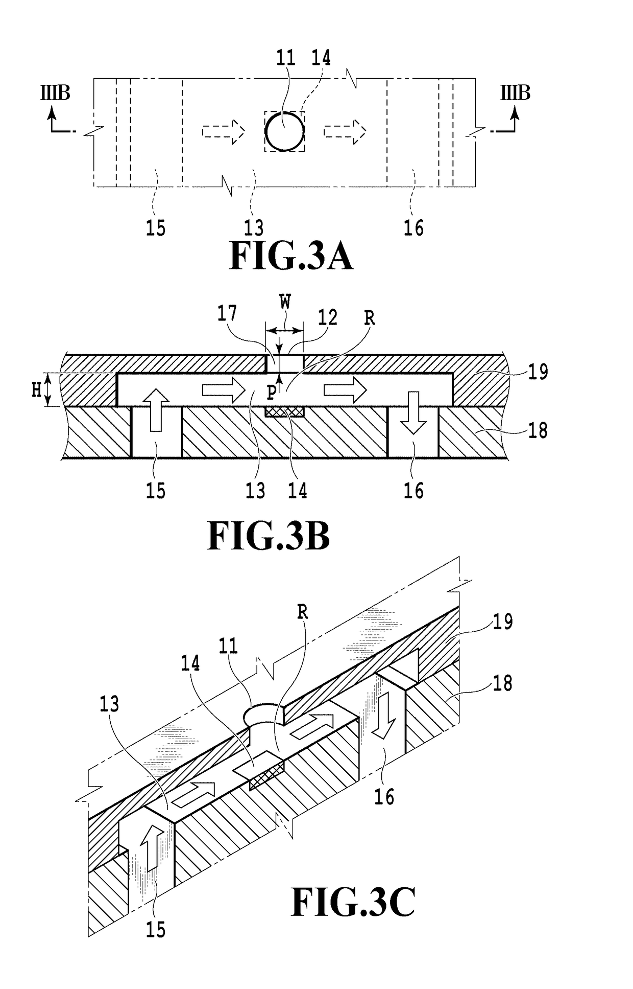
In a circulating system which circulates liquid within a liquid ejecting head, thickening of liquid in the vicinity of an ejection port can be more securely suppressed. The ejection port includes a first ejection port disposed in an upstream side in an ejecting direction of ink and a second ejection port disposed in a downstream side in the ejecting direction. The second ejection port includes an enlarged diameter portion whose diameter is enlarged in a radially outward manner from at least a part of an opening edge portion of the first ejection port.

Description

BACKGROUND OF THE INVENTIONField of the Invention[0001]The present invention relates to a liquid ejecting head which can eject liquid such as ink and a liquid ejecting apparatus.Description of the Related Art[0002]In a print head (liquid ejecting head) included in an inkjet printing apparatus as a liquid ejecting apparatus, ink in the vicinity of an ejection port thickens as a result of evaporation of a volatile component included in ink from the ejection port in which liquid ink is to be ejected. In a case where such thickening of ink occurs, an ink ejection speed and an ink ejecting direction from the ejection port are changed and the landing accuracy of ink droplets may be possibly affected. Particularly, in a case where pause time of not ejecting ink is long, the increase of the viscosity of ink is remarkable and the solid component of ink adheres to the vicinity of the ejection port, thereby increasing fluid resistance of ink and possibly inducing failure of ink ejection.[0003]...

Claims


Application Information

Patent Timeline
IPC IPC(8): B41J2/14
CPCB41J2/1433B41J2002/14419B41J2/01B41J2/1404B41J2002/14403B41J2002/14475B41J2202/12B41J2/14201B41J2/145
Inventor NAKAGAWA, YOSHIYUKIYAMAZAKI, TAKUROYAMADA, KAZUHIRONAKAKUBO, TORU
Owner CANON KK
Learn More