Heat exchanger cleaning installation and associated system

a technology of heat exchanger and installation system, which is applied in the direction of cleaning hollow articles, non-rotary devices, chemistry apparatus and processes, etc., can solve the problems of poor economic performance of the pump, the internal surface of the tube bundle which is passed through by the coolant, and the cost of the device is also quite high, so as to achieve the effect of less cost and simple managemen

Active Publication Date: 2018-12-27
EUGENE B
View PDF21 Cites 2 Cited by
  • Summary
  • Abstract
  • Description
  • Claims
  • Application Information

AI Technical Summary

Benefits of technology

[0013]The abovementioned installation comprises neither pump nor motorized valves on the circuit of the cleaning bodies, which makes the installation more reliable than previously. Indeed, the presence of motorized valves and their repeated implementation induces, over time, malfunctions which require mainten

Problems solved by technology

Over time, the internal surface of the tubes of the tube bundle which are passed through by the coolant are subject to fouling which can take the form of scaling, silt deposits, a film of biological growths or a combination

Method used


Image

  • Heat exchanger cleaning installation and associated system
  • Heat exchanger cleaning installation and associated system
  • Heat exchanger cleaning installation and associated system

Examples


Embodiment Construction

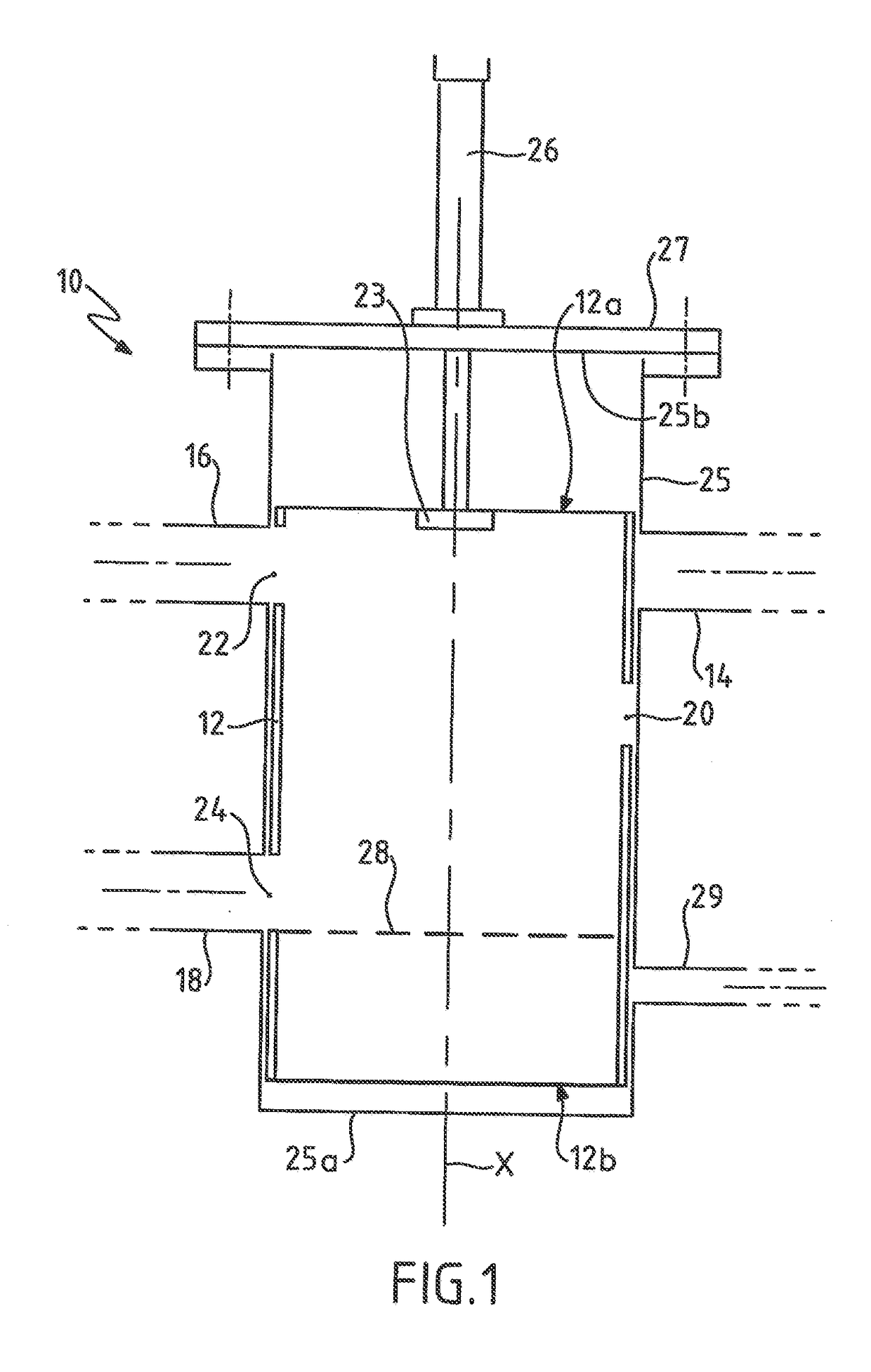
[0049]FIG. 1 illustrates schematically and in isolation a system 10 for recovering and reinjecting cleaning bodies according to an embodiment of the invention.

[0050]In this embodiment, the cleaning bodies are solid cleaning elements that are known per se which are likely to be circulated permanently in the installation of FIG. 2 described hereinbelow and, in particular, in a heat exchanger of this installation, for the continuous cleaning thereof.

[0051]In practice, the cleaning bodies are balls of foam rubber, the diameter of which is slightly greater than the internal diameter of the tubes of the heat exchanger to be cleaned, and whose density, in the soaked state, is similar to that of water.

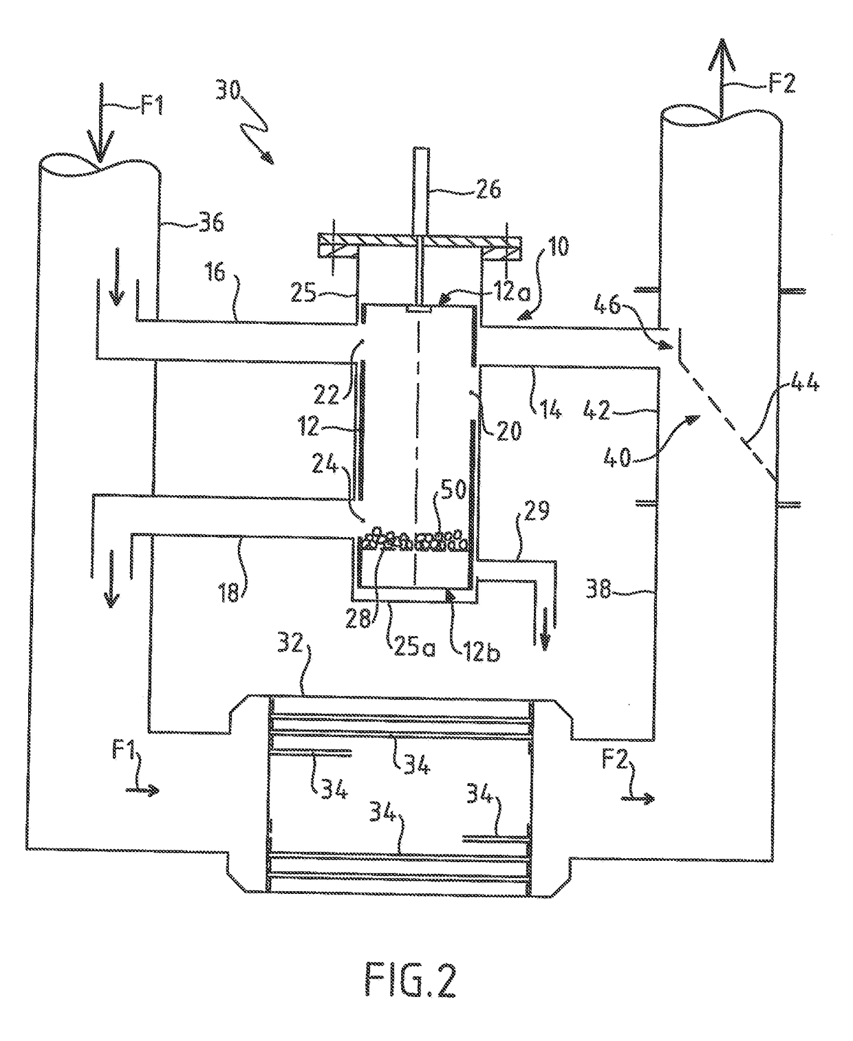
[0052]A management of these cleaning bodies should be provided, for example, in the installation of FIG. 2, that is to say not only an effective circulation thereof in the heat exchanger, but also control of the number thereof and possibly their dimensions (thus if necessary making it possible...


PUM


Abstract

A cleaning installation of a heat exchanger includes a heat exchanger linked upstream to an intake duct for a fluid and downstream to an outlet duct for the fluid. A system is provided for recovering cleaning bodies from the outlet duct after cleaning of the exchanger by the bodies and for reinjecting bodies into the intake duct. The system includes a member capable of being displaced between a first position in which the system is configured to recover and contain cleaning bodies in the mobile member, and a second position in which the system is configured to take fluid from the intake duct and reinject, into this duct, via the mobile member and under the action of the fluid taken, cleaning bodies contained in the member.

Description

RELATED APPLICATION[0001]This application claims the benefit of priority from French Patent Application No. 17 55778, filed on Jun. 23, 2017, the entirety of which is incorporated by reference.BACKGROUNDField of the Invention[0002]The present invention relates to a heat exchanger cleaning installation.Description of Related Art[0003]As is known, tubular heat exchangers have an efficiency which depends on the coefficient of heat exchange through the wall of the tubes. Over time, the internal surface of the tubes of the tube bundle which are passed through by the coolant are subject to fouling which can take the form of scaling, silt deposits, a film of biological growths or a combination thereof.[0004]To avoid this fouling which impacts the energy efficiencies of such an exchanger, balls made of foam rubber, which have a density equal to that of water once the air contained in the foam is eliminated, are passed into the tubes. These balls have a diameter slightly greater than the int...

Claims


Application Information

Patent Timeline
IPC IPC(8): F28G1/12B08B9/057
CPCB08B9/0551B08B9/0552B08B9/057F28G1/12F28G15/04B08B2209/055F28G1/00
Inventor JACKSON, PHILIP EUGENE, DOUGLAS
Owner EUGENE B
Why Eureka
Try Eureka