Battery assembly

a battery and assembly technology, applied in the direction of cell components, cell component details, coupling device connections, etc., can solve the problems of significant reliability challenge, design suffers from poor reliability and flexibility, whole assembly fails, etc., and achieves improved energy density, power density and reliability. the effect of improving reliability and safety

Inactive Publication Date: 2006-08-10
YAO LI HO
View PDF14 Cites 107 Cited by
  • Summary
  • Abstract
  • Description
  • Claims
  • Application Information

AI Technical Summary

Benefits of technology

[0014] A battery assembly includes one or more batteries; wherein each battery containing S×P (S times P) cells has the structure of two current collectors connecting P cell strings in parallel. Each cell string is comprised of S cells connected in series. The battery is completed by connecting P cells in corresponding positions in each of the P strings with metallic connectors. These connectors are made in a centipede shape so that only S pieces of them will serve to make all the necessary connections in a S×P battery. The management circuitry of a battery assembly is simplified to a level that it is realistic for the assembly to be made from small cells to improve on safety. The energy density, power density and reliability are also improved. The net result is a battery assembly that is simple to produce and suitable for high power applications such as EV or HEV.

Problems solved by technology

Although simple in concept, this design suffers from poor reliability and flexibility.
If any of the cells or cell connections fails, the whole assembly fails, which presents a significant reliability challenge.
Additionally, lead-acid batteries are very bulky.
Electric vehicles usually have limited space set aside for their battery assemblies.
Sparing two hundred fifty liters of volume for the 25,000 watt-hours necessary to run an electric vehicle's power source will not leave much flexibility for EV design.
On top of the above-mentioned issues, lead-acid batteries are inordinately heavy.
In addition to cost and safety concerns, the lack of a battery design that can efficiently harness the cell's power and energy is the primary reason for the slow commercialization.
Therefore, the larger the amount of energy contained in each individual cell, the lower the weight of the final assembly.
For comparison purposes, a typical notebook computer battery has a maximum power of less than 200 w. Even at this low level of power, the notebook computer battery's assembly can overheat if not properly designed.
In extreme situations, a battery can cause a fire or explosions that may spread throughout the entire pack to create a major safety incident.
Although they have the advantages of high specific energy and power densities, the application to EV or HEV still lags behind nickel metal hydride cells due to safety matters.
But, the conventional thinking argues that building large battery assemblies from small cells would inevitably be ineffective due to a large number of connector required, which will result in both reduced specific energy and reliability.
However the reliability is an issue.
The power density suffers because of this as well.
When this design is applied to lithium-ion cells, the battery charge / discharge management system is complex.
If the range is exceeded during use, the cells can suffer reduced life and capacity, or even become a safety hazard.
In this assembly design described, S×P (S times P) cells need to be controlled individually, which would be a cumbersome task for large assemblies.
Unfortunately, with this design, each parallel group (72) will be required to gather its own current by heavy current collectors (73), which will make the assembly heavy.
Clearly, a design suitable for EV or HEV batteries that possesses a combination of high energy, high power, high reliability and high level of safety is lacking.

Method used


Image

  • Battery assembly
  • Battery assembly
  • Battery assembly

Examples


example 1

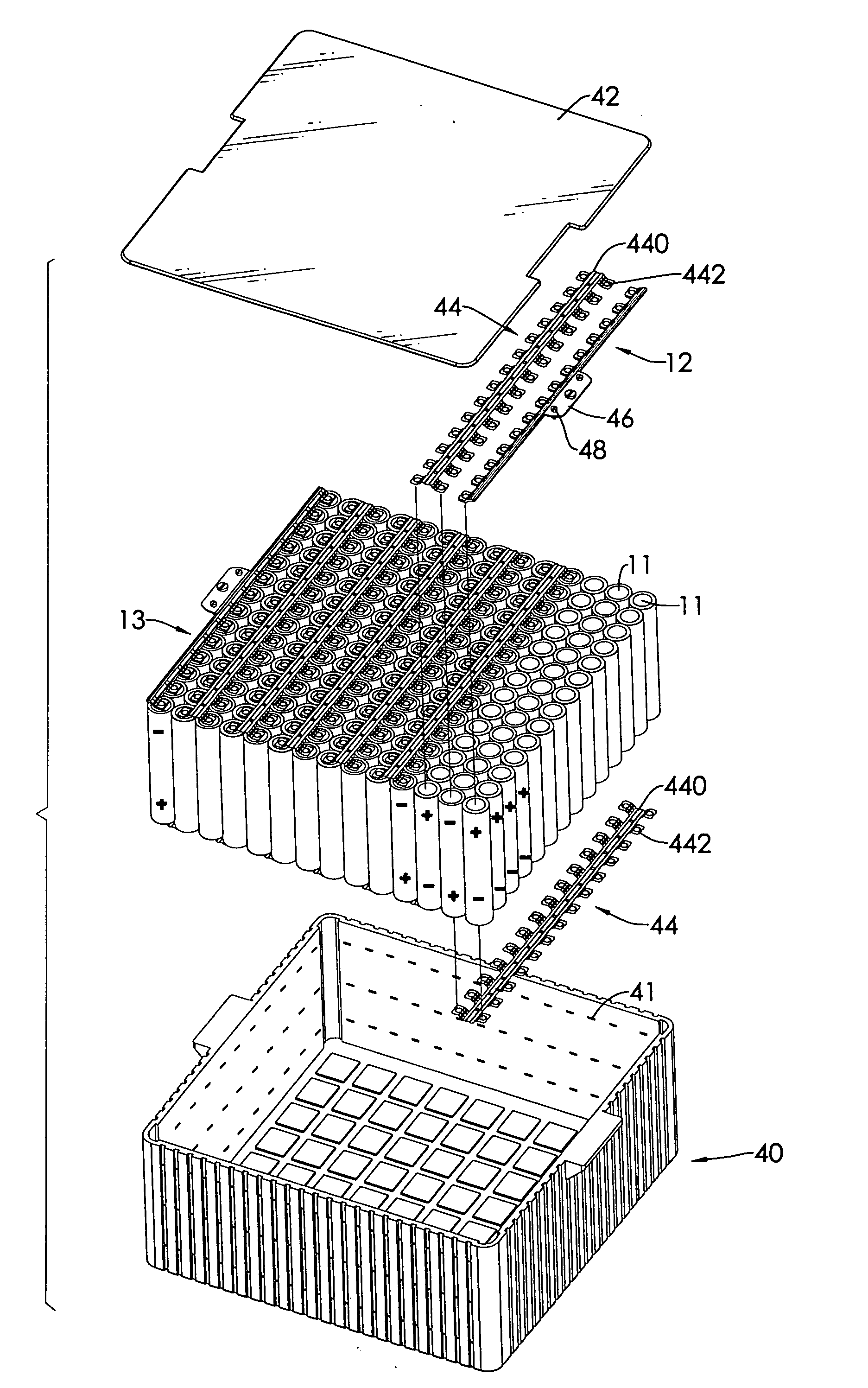
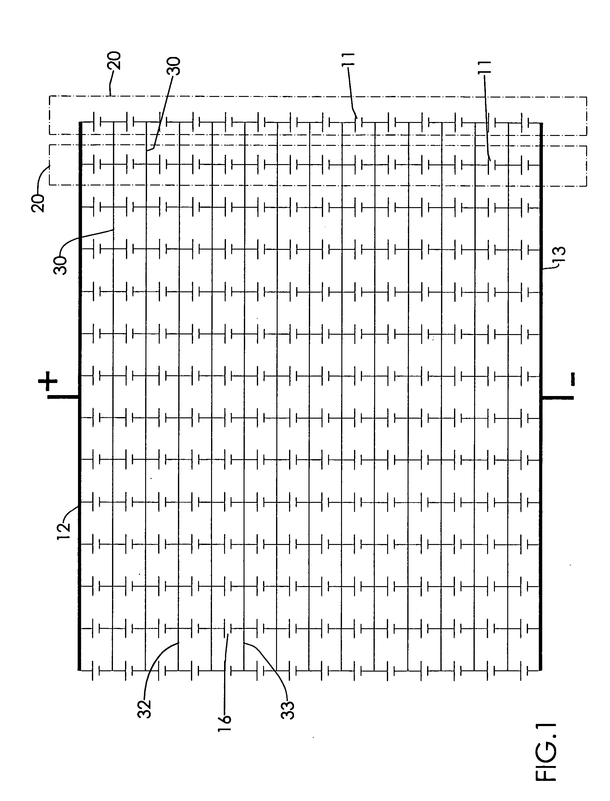
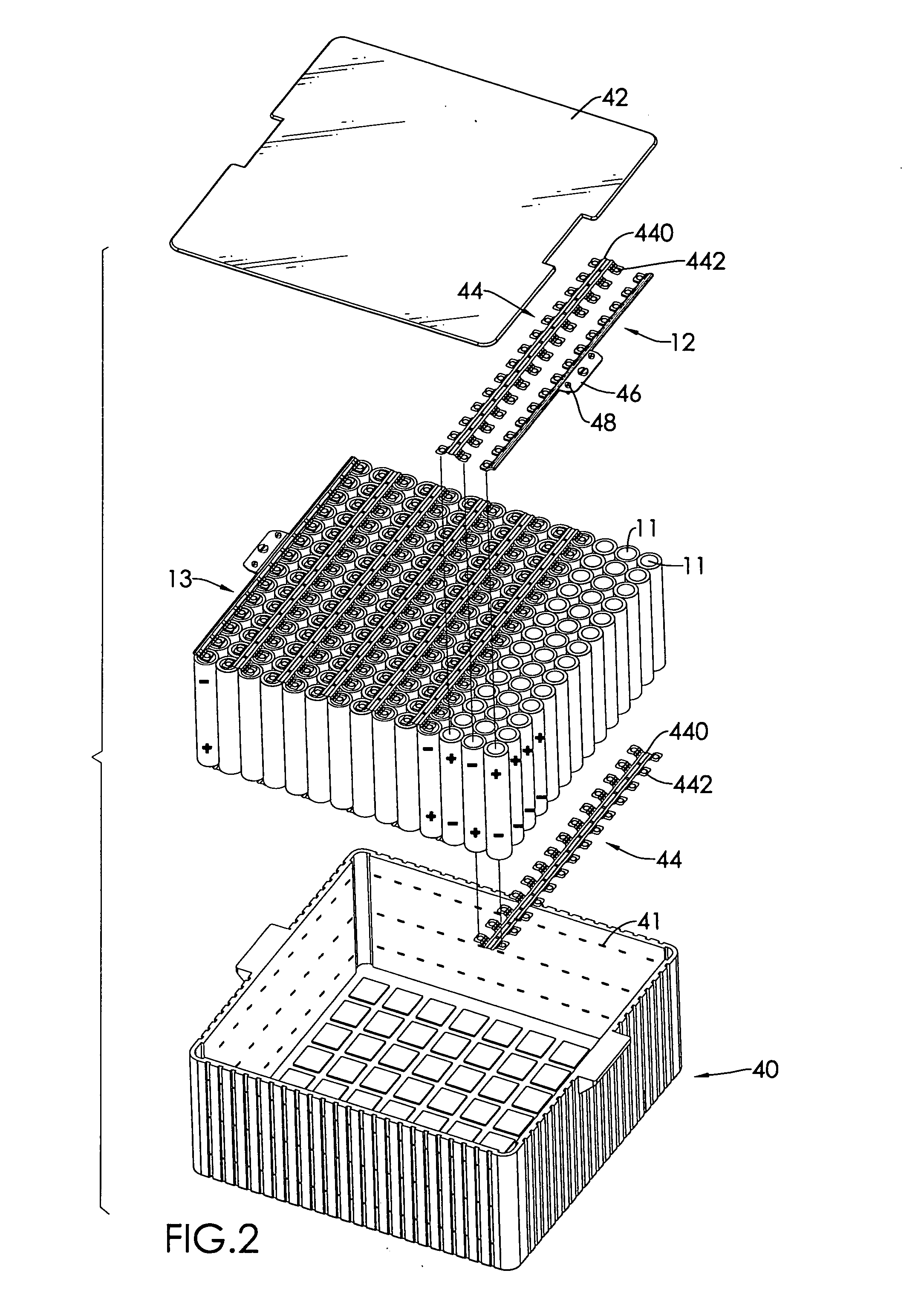
[0045] A battery of 50×20 configuration and 185V is made by connecting 1,000 lithium-ion cells, each having 3.0 ampere-hour capacity, 100.1 g weight, 2.7 cm diameter and 7.0 cm height, with pure nickel conductive plates stamped out of 10-micron thick nickel sheets as described in this invention. The DC resistance of the cells measured at 50% depth of discharge is 14.2 milliohms. Two pure copper pieces, 0.6 cm×0.35 cm×54 cm, serve as current collectors. The combined cell weight is 10,010 g grams and the battery weight is 10,153 grams; only 1.43% weight is added by the connectors. The discharge capacity, DC resistance and loaded voltage at 30 amperes and 50% depth of discharge are measured and listed in Table I. The power output of this battery is higher than 105,540 w.

CellBattery, measuredBattery, predictedCapacity3.0Ah60Ah60AhDC resistance14.2milliohm35.6milliohm35.5milliohmLoad Voltage,3.52V175.9V176.0V10 C

example 2

[0046] A battery assembly is structured by connecting in series two of the batteries in example 1. The nominal voltage of the assembly is 370 volts and the power output is larger than 211,080 watts.

example 3

[0047] A battery is made as in example 1 but a failure is simulated by disconnecting a weld to cell 12. The discharge capacity at 60 amperes current and DC resistance at 50% depth of discharge are measured to be 57 ampere-hours and 35.7 milliohms. The load voltage at 10 C is 175.7 volts, a power loss of mere 0.2% at this rate. When a second failure is created by disconnecting a cell 13, the discharge capacity remains at 57 ampere-hours. The load voltage is 175.5 volts, a power loss of 0.4%.


PUM

PropertyMeasurementUnit
distanceaaaaaaaaaa
volumeaaaaaaaaaa
volumeaaaaaaaaaa

Abstract

A battery pack includes multiple power bus lines connecting a quantity of cell strings in parallel, wherein each cell string includes multiple cells connected in series. The battery pack further has multiple conductors providing electrical communication between the cell strings such that a cell in one cell string is connected in parallel with a cell in other battery strings.

Description

BACKGROUND OF THE INVENTION [0001] 1. Field of the Invention [0002] The invention relates to a battery assembly composed of multiple electrochemical cells networked in a configuration suitable for powering electric vehicles (EVs) or hybrid electric vehicles (HEVs). This configuration not only improves the reliability of the power source, but also increases the power and energy densities of the battery assembly. [0003] 2. Related Art [0004] Battery-powered vehicles such as electric vehicles (EVs) or hybrid electric vehicles (HEVs) contain one or more batteries that are constructed from multiple electrochemical cells. For example, a conventional lead-acid battery made for vehicle applications contains six cells connected in series inside a housing to form a twelve-volt power source. In most cases, neither the voltage nor the energy content of a single battery will be sufficient to power passenger electric vehicles; therefore, a solution is to connect a quantity of such batteries in se...

Claims


Application Information

Patent Timeline
Patent Type & Authority Applications(United States)
IPC IPC(8): H01M2/24H01M2/02H01M2/04H01M8/24H01M50/529H01M50/213H01M50/503H01M50/505H01M50/509H01M50/522H01M50/526
CPCH01M2/1077H01M2/206H01M8/2405H01M10/0525H01M10/345Y02E60/12Y02T10/7011H01M6/42H01M10/052H01M10/0565H01R13/22H01R31/085H01M10/4207Y02E60/50H01M50/522H01M50/526H01M50/213H01M50/509H01M50/505H01M50/503Y02E60/10H01M50/20H01M8/2465H01M8/241
Inventor YAO, LI-HO
Owner YAO LI HO
Why Eureka
Try Eureka