
Surge protector, and release mechanism and base thereof

a technology of release mechanism and surge protector, which is applied in the direction of emergency connection, protective switch details, protective switch using micromechanics, etc., can solve the problem that the wiring cannot be completely cut o

Active Publication Date: 2018-12-27
SHANGHAI CHENZHU INSTR +2
View PDF0 Cites 0 Cited by
  • Summary
  • Abstract
  • Description
  • Claims
  • Application Information

AI Technical Summary

Benefits of technology

The present invention provides a release mechanism and a base for a surge protector. The release mechanism includes an internal box body, a function rotating member, an elastic driving device, a first and second electrical connection pin, and a bridge bracket. The function rotating member is sheathed on the fixed column and disposed between the varistor and the bridge bracket. The elastic driving device drives the function rotating member to rotate around the fixed column to quickly release the varistor. The base includes a mechanical connecting structure with different linkages and one micro switch and one slider. The motive of this invention is to improve the safety and reliability of the surge protector, provide a simple mechanism, and lower the cost. Additionally, the invention provides a release mechanism for a surge protector that allows for quick and effective feedback to a control system for each time of release.

Problems solved by technology

If the distance between them is too short, the wiring cannot be cut off completely.

Method used


Image

  • Surge protector, and release mechanism and base thereof
  • Surge protector, and release mechanism and base thereof
  • Surge protector, and release mechanism and base thereof

Examples


Embodiment Construction

[0052]The technical contents of the present invention will become apparent with the detailed description of preferred embodiments accompanied with the illustration of related drawings as follows. It is noteworthy that the preferred embodiments are provided for illustrating this disclosure rather than restricting the scope of the disclosure.

[0053]Preferred embodiments of the release mechanism, the base and the surge protector of this disclosure will be described and illustrated according to the accompanied drawings as follows.

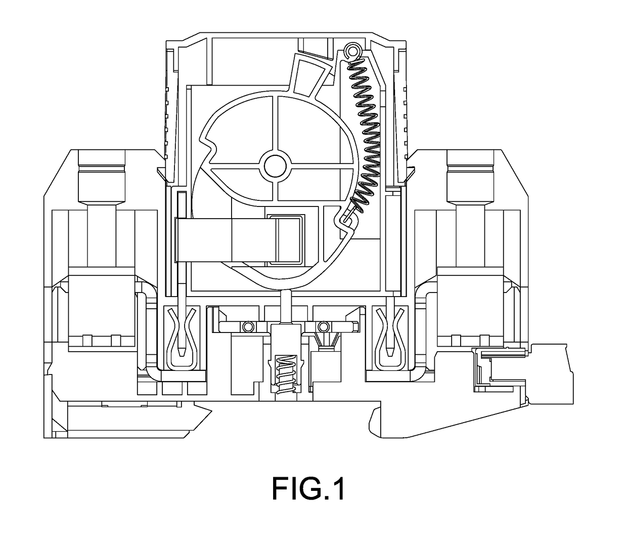
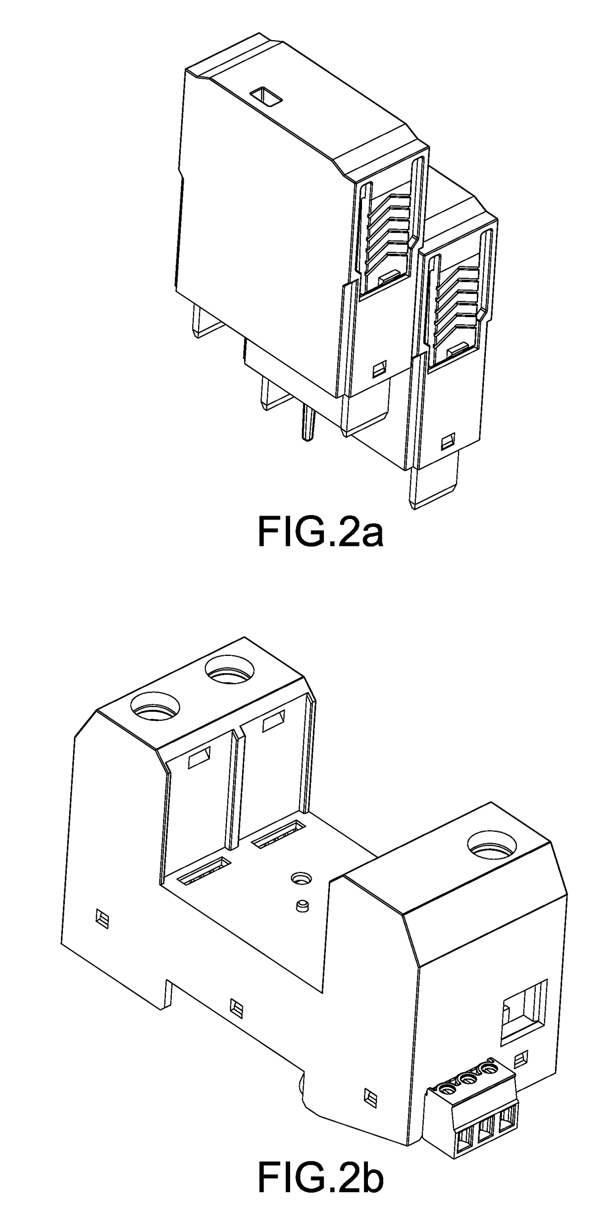
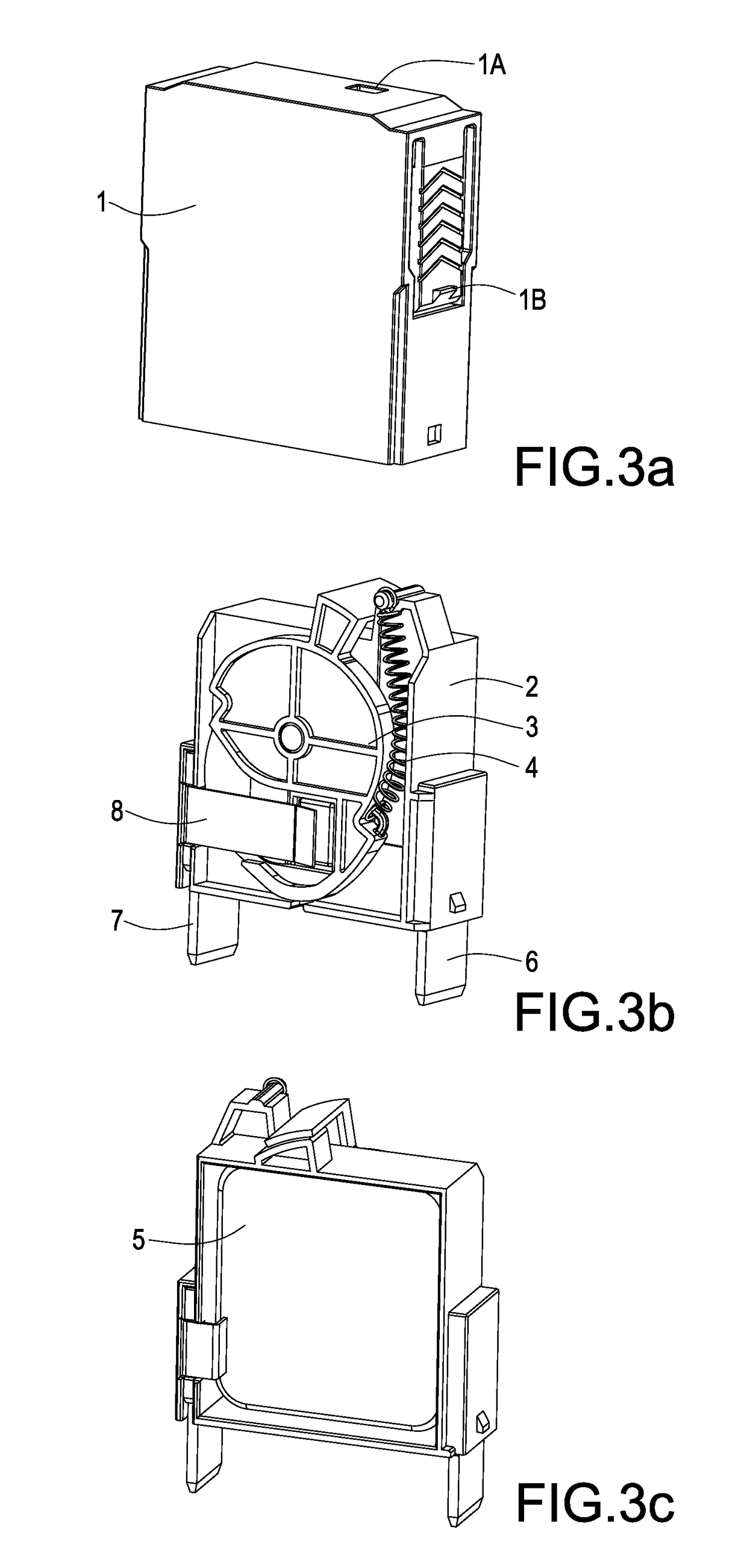
[0054]With reference to FIGS. 1-7 for a release mechanism of a surge protector, the release mechanism comprises an external box body 1, an internal box body 2, a function rotating member 3, an elastic driving device 4, a first electrical connection pin 6, a second electrical connection pin 7, and a bridge bracket 8.

[0055]With reference to FIGS. 4a and 4b, the internal box body 2 comprises: a panel, a function rotating member placement slot 2A, a fixed column 2B,...


PUM


Abstract

A release mechanism for surge protectors includes a first electrical connection pin (6) soldered with a varistor's second electrode (5B), a function rotating member (3) sheathed on a fixed column (2B and installed between a varistor (5) and a bridge bracket (8), an elastic driving device (4) fixed into an internal box body (2), and a bridge bracket (8) fixed to a second electrical connection pin (7) in the internal box body (2). If the varistor (5) is not released, then the bridge bracket (8) will be passed through a soldering window (3C) and soldered with a varistor's first electrode (5A), or else the elastic driving device (4) will drive the function rotating member (3) to rotate around the fixed column (2B). An arc shield plate (3F) exposed from a failure status indicating area (2N) for triggering a remote linkage rod (9) shields the bridge bracket (8) and electrode (5A).

Description

FIELD OF THE INVENTION[0001]This disclosure relates to a surge protector, and more particularly to a release mechanism and a base of the surge protector.BACKGROUND OF THE INVENTION[0002]A surge protector is generally applied in an electric circuit and used at home, office, or factory to prevent electric equipment's from being damaged by transient overvoltage. When the electric circuit or a communication circuit produces a peak current or voltage by external interference, the surge protector is capable of conducting shunts in a very short time to avoid damaging other equipments in the circuit due to an electric surge.[0003]In general, a surge protector includes a metal oxide varistor (which is one of the varistors), and the varistor may be aged after a long time of use and generates heat easily. To prevent accidents such as a fire caused by the rise of temperature, the surge protector usually comes with a release mechanism connected in series with the varistor, so that when the tempe...

Claims


Application Information

Patent Timeline
IPC IPC(8): H01H71/14H01H71/02H01H71/04H01H71/10H01H15/02
CPCH01H71/14H01H71/0207H01H71/04H01H71/025H01H2207/036H01H15/02H01H2235/01H01H2071/008H01H2207/02H01H71/1009H01C7/12H01H37/08H01H37/76H01H2037/762H01C7/126
Inventor ZHAI, CHUNPOCHEN, KEQIWU, SHANG-TSAI
Owner SHANGHAI CHENZHU INSTR
Learn More