Tape format magnetoelastic resonator markers

a magnetoelastic resonator and tape format technology, applied in the direction of transformers/inductances, magnetic cores, magnetic bodies, etc., can solve the problems of limited detection range and frequency stability of such conventional mel resonators, and achieve the effect of reducing the loading

Active Publication Date: 2019-01-10
3M INNOVATIVE PROPERTIES CO
View PDF1 Cites 2 Cited by
  • Summary
  • Abstract
  • Description
  • Claims
  • Application Information

AI Technical Summary

Benefits of technology

[0010]In another aspect, the hinge geometry is configured to

Problems solved by technology

However, the detection range and frequency stability

Method used


Image

  • Tape format magnetoelastic resonator markers
  • Tape format magnetoelastic resonator markers
  • Tape format magnetoelastic resonator markers

Examples


Embodiment Construction

[0024]In the following description, reference is made to the accompanying drawings, which form a part hereof, and in which is shown by way of illustration specific embodiments in which the invention may be practiced. In this regard, directional terminology, such as “top,”“bottom,”“front,”“back,”“leading,”“forward,”“trailing,” etc., is used with reference to the orientation of the Figure(s) being described. Because components of embodiments of the present invention can be positioned in a number of different orientations, the directional terminology is used for purposes of illustration and is in no way limiting. It is to be understood that other embodiments may be utilized and structural or logical changes may be made without departing from the scope of the present invention. The following detailed description, therefore, is not to be taken in a limiting sense, and the scope of the present invention is defined by the appended claims.

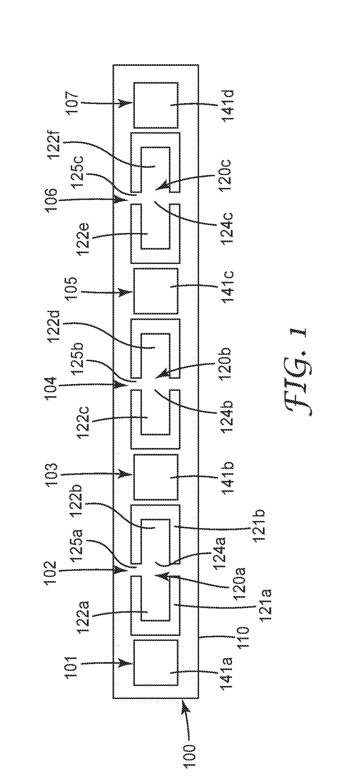
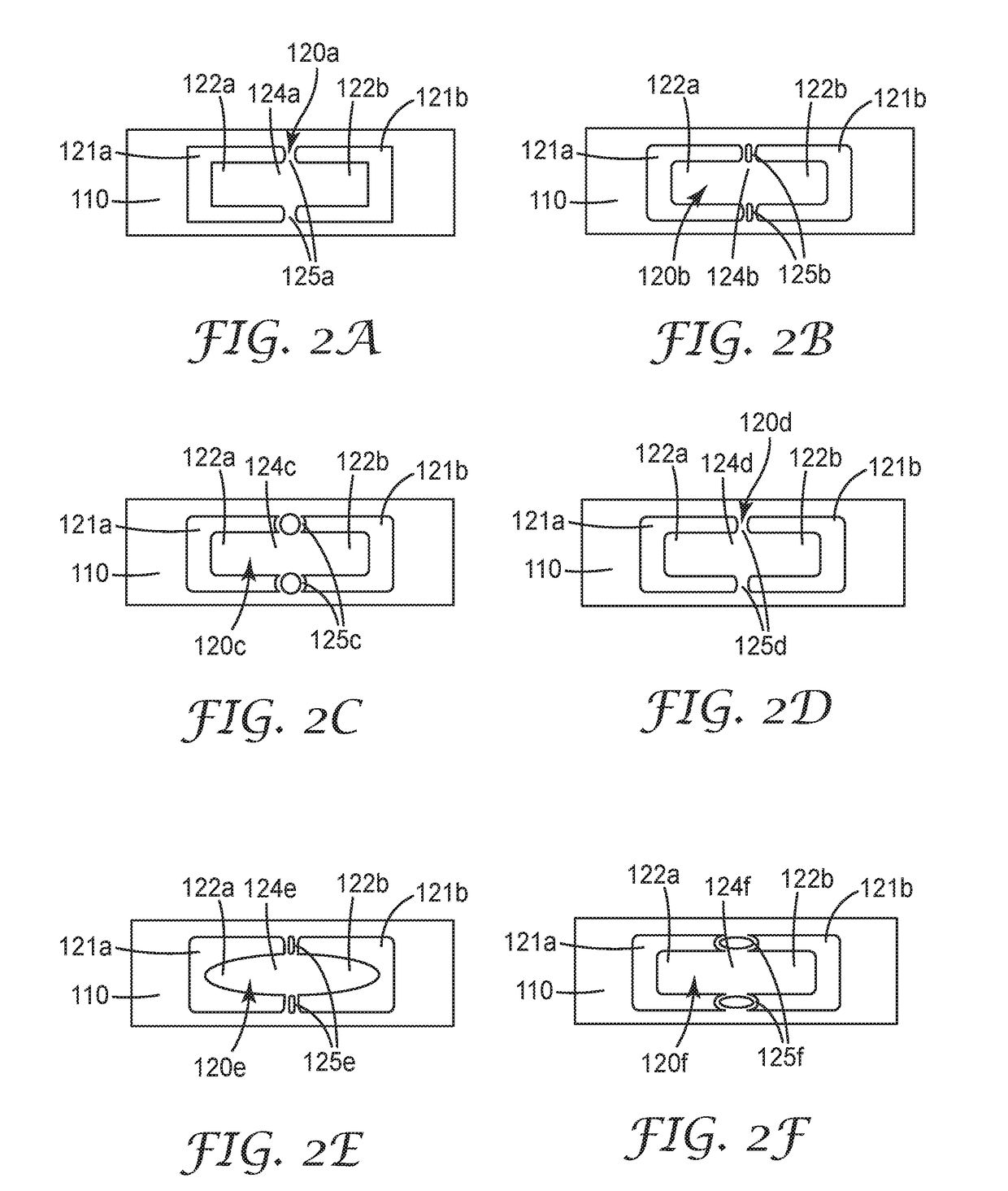
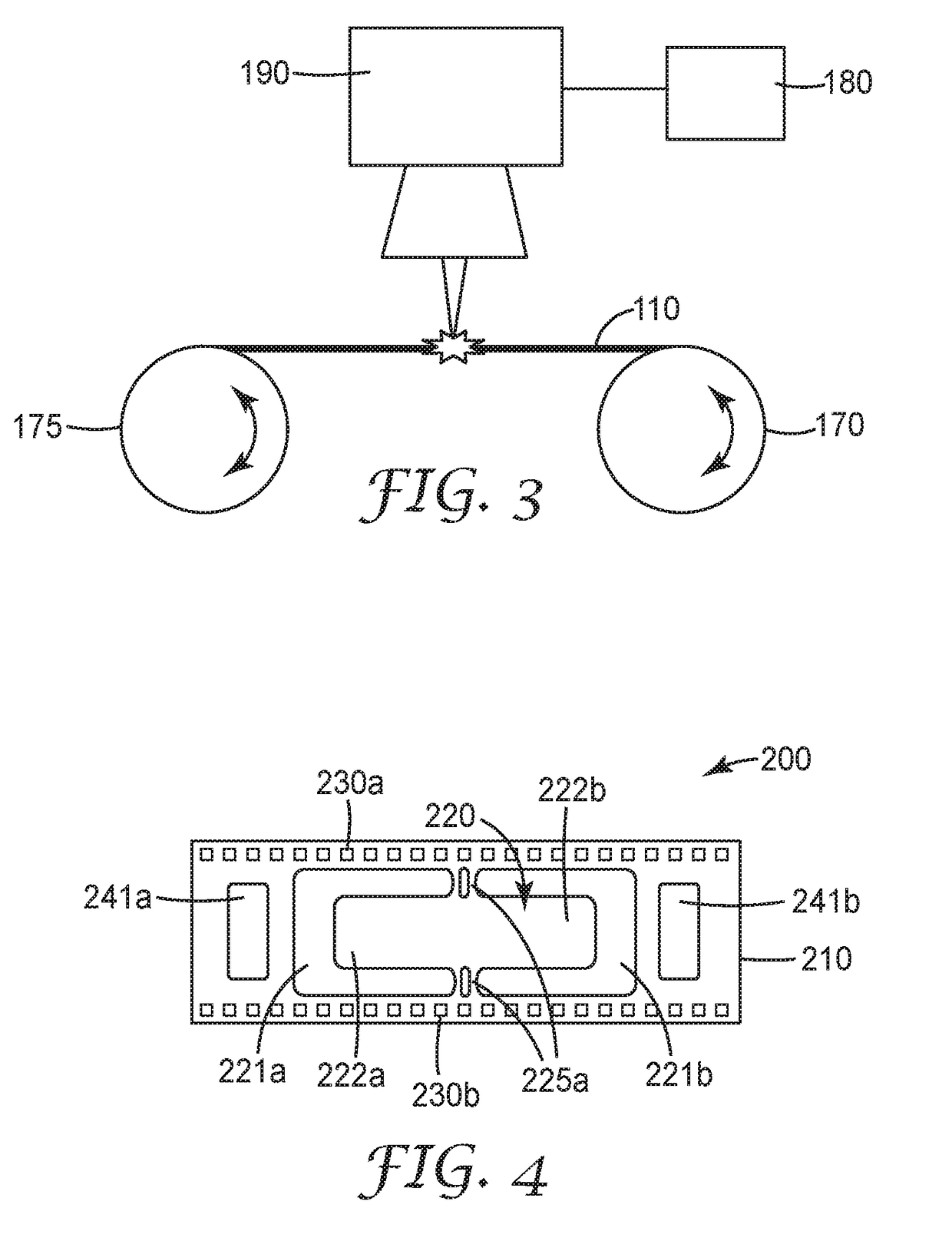
[0025]A tape format magnetoelastic (MEL) resonator d...


PUM


Abstract

A tape format magnetoelastic resonator device comprises a continuous ribbon of amorphous magnetic material having a plurality of separate, hinged magnetoelastic resonator strips formed from the ribbon, linearly displaced along a longitudinal axis of the ribbon, wherein each magnetoelastic resonator strip is configured to couple to an external magnetic field at a particular frequency and convert the magnetic energy into mechanical energy, in the form of oscillations.

Description

BACKGROUND[0001]Magneto-mechanical resonators (MMRs), also referred to as magnetoelastic (MEL) resonators, are well known and have been used in retail security applications for decades. In addition, MEL resonators are also suitable for buried infrastructure due to their low cost, low profile and flexible components. They can be configured as stand-alone markers or physically attached to an underground pipe or utility. They can be used to identify a buried asset and its location accurately. For example, see US 2012 / 068823; US 2012 / 0325359; and US 2013 / 0099790, each of which is incorporated herein by reference in its entirety.[0002]However, the detection range and frequency stability of such conventional MEL resonators can be limited.SUMMARY OF THE INVENTION[0003]In a first aspect of the invention, a tape format magnetoelastic resonator device comprises a continuous ribbon of amorphous magnetic material having a plurality of separate, hinged magnetoelastic resonator strips formed from...

Claims


Application Information

Patent Timeline
IPC IPC(8): G01V15/00G06K19/06H01F1/04H03H9/24
CPCG01V15/00G06K19/06196G01R33/18H03H9/24H01F1/04H01F1/15333G01R33/02G01R33/063H01F1/15308H01F27/25H01F1/153H01F7/02H01P7/08
Inventor SHOEMAKER, CURTIS L.DOANY, ZIYAD H.WANG, DING
Owner 3M INNOVATIVE PROPERTIES CO
Why Eureka
Try Eureka