
Wire housing protector

Inactive Publication Date: 2019-01-10
SUMITOMO WIRING SYST LTD
View PDF11 Cites 6 Cited by
  • Summary
  • Abstract
  • Description
  • Claims
  • Application Information

AI Technical Summary

Benefits of technology

The present invention is a new design for a wire housing protector that solves problems with previous designs. The new design allows for more electric wires to fit within the protector, improves assembly, and makes it easier to check that the locking mechanism is working properly.

Problems solved by technology

However, wire housing protectors having the foregoing conventional structure have an inherent problem in that, because the locking mechanism protrudes outward from a sidewall of the protector body, some of the capacity of the wire housing portion of the protector body is sacrificed so as to secure space for the locking mechanism.
At times, conventionally structured wire housing protectors have been unable to meet this requirement sufficiently.
In particular, there have been cases in which the lid could not easily interlock with the protector body because there were too many electric wires for the capacity of the wire housing protector.
However, wire accommodation protectors having a structure in which the locking mechanism is provided inside the side wall of the protector body in this way suffer from an inherent problem.
In particular, the opening area of the elastic projecting piece insertion hole that opens in the upper surface of the side wall of the protector body is inevitably made small, and the elastic projecting piece insertion hole is difficult to be located as well, and therefore the task of inserting the elastic projecting piece into the elastic projecting piece insertion hole is difficult.
Furthermore, since the locking mechanism is constituted by the engagement protrusion formed at the leading end of the elastic projecting piece and the engagement portion formed inside the elastic projecting piece insertion hole, it is difficult to visually check the engagement state between the engagement protrusion and the engagement portion from the outside as well.

Method used


Image

  • Wire housing protector
  • Wire housing protector
  • Wire housing protector

Examples


Embodiment Construction

[0025]Hereinafter, embodiments of the present application will be described with reference to the drawings.

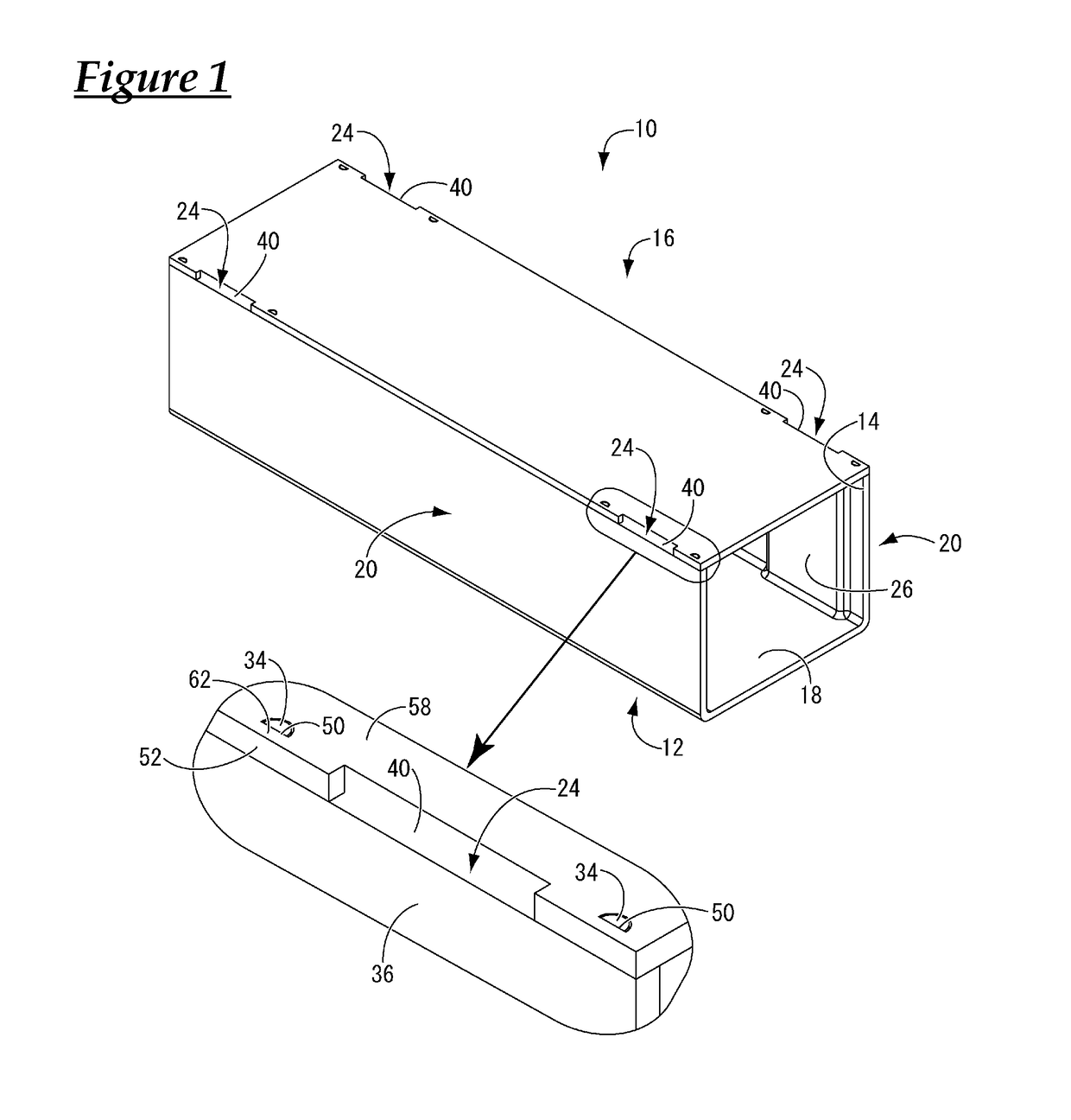
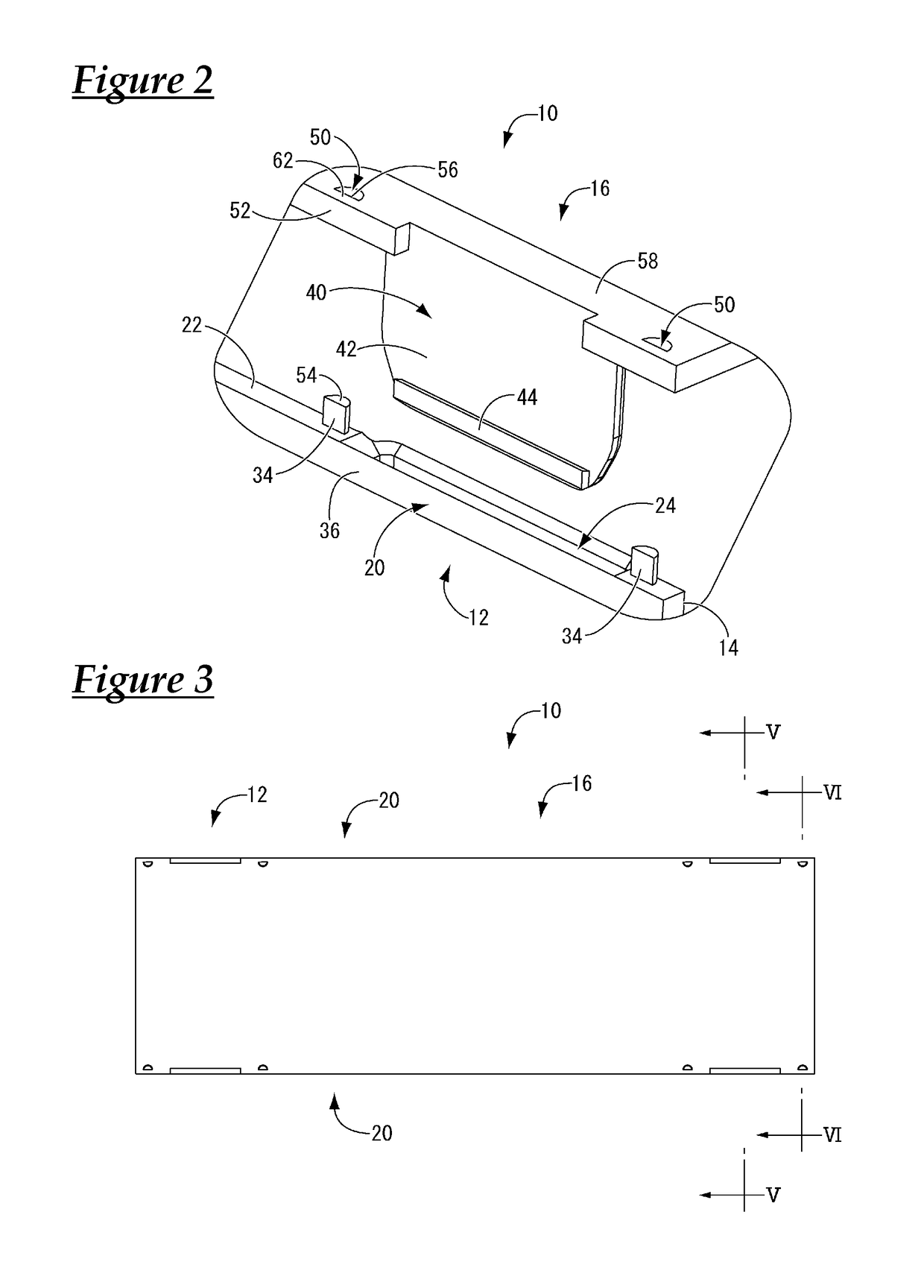
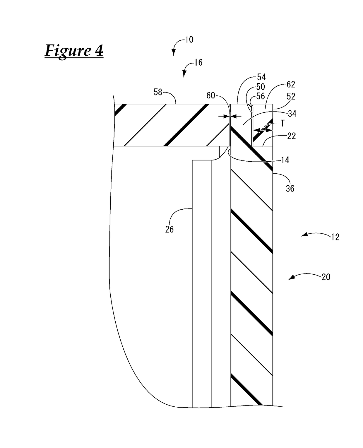
[0026]First, a wire housing protector 10 according to a first embodiment of the present invention is shown in FIGS. 1 to 5. The wire housing protector 10 is constituted by a protector body 12 extending in the shape of a trough and a lid 16 that covers the upper opening 14 of the protector body 12. When in use, the wire housing protector 10 accommodates a wire harness (not shown) laid through the protector body 12. Also, in the following description, “upward” refers to the upward direction in FIG. 1, “downward” refers to the downward direction in FIG. 1, “forward” refers to the leftward direction in FIG. 1, and “backward” refers to the rightward direction in FIG. 1.

[0027]As shown in FIGS. 1 and 2, the protector body 12 is configured to extend in the shape of a trough, includes a bottom wall 18 and a pair of sidewalls 20 rising upright from both sides of the bottom wall 18, and i...


PUM


Abstract

A wire housing protector having a structure in which the volume of electric wires that can be accommodated can be increased by downsizing the locking mechanism, the workability at the time of assembly can be improved, and whether members in the locking mechanism are engaged properly can be more easily confirmed. A fitting protrusion that protrudes toward a lid side is provided at an upper surface of the side wall of the protector body in the vicinity of the elastic projecting piece insertion hole, and the lid is provided with a fitting protrusion housing hole that passes through the lid at a position corresponding to the fitting protrusion in plan view.

Description

TECHNICAL FIELD[0001]The present invention relates to a wire housing protector for holding multiple electric wires laid therethrough that are routed inside an automobile or the like.BACKGROUND ART[0002]Conventionally, in the electric system of automobiles or the like, multiple routed electric wires are laid through and held within a wire housing protector and secured at suitable locations in order to protect the electric wires from external members that might otherwise interfere with the electric wires and restrict the routing of the electric wires.[0003]Incidentally, as described in JP H06-70415U (Patent Document 1) for example, such a wire housing protector is constituted by a trough-shaped protector body and a lid that covers the upper opening of the protector body. Once multiple electric wires are laid through the protector body, the lid is fixed to the protector body by a locking mechanism that protrudes from a sidewall of the protector body. In this way, the protector is capab...

Claims


Application Information

Patent Timeline
IPC IPC(8): H02G3/04
CPCH02G3/0418B60R16/0215H02G3/0487H01B7/40H02G3/04
Inventor SUENAGA, RYO
Owner SUMITOMO WIRING SYST LTD
Learn More