
Modular apparatus for high voltage direct-current transmission system

a high-voltage direct-current transmission and module technology, applied in the direction of electrical apparatus casings/cabinets/drawers, electrical power transfer ac networks, printed circuit board receptacles, etc., can solve the problems of difficult difficult to check the state of control boards, etc., to achieve easy maintenance of control boards, stable signal connection, and minimize the effect of surroundings

Active Publication Date: 2016-10-06
HYOSUNG HEAVY IND CORP
View PDF17 Cites 1 Cited by
  • Summary
  • Abstract
  • Description
  • Claims
  • Application Information

AI Technical Summary

Benefits of technology

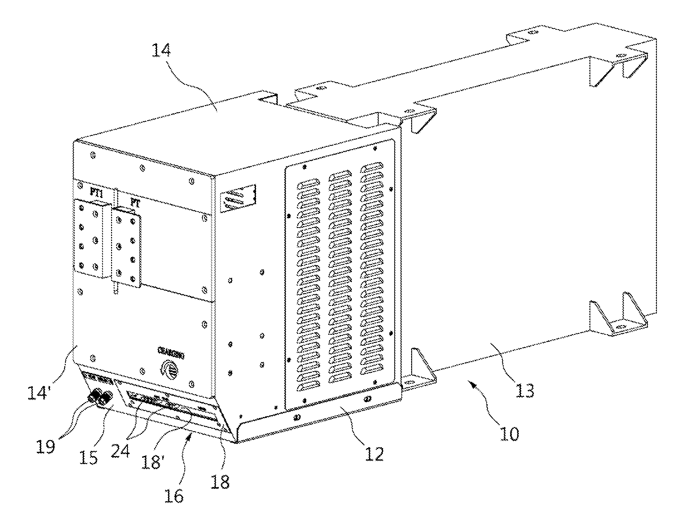
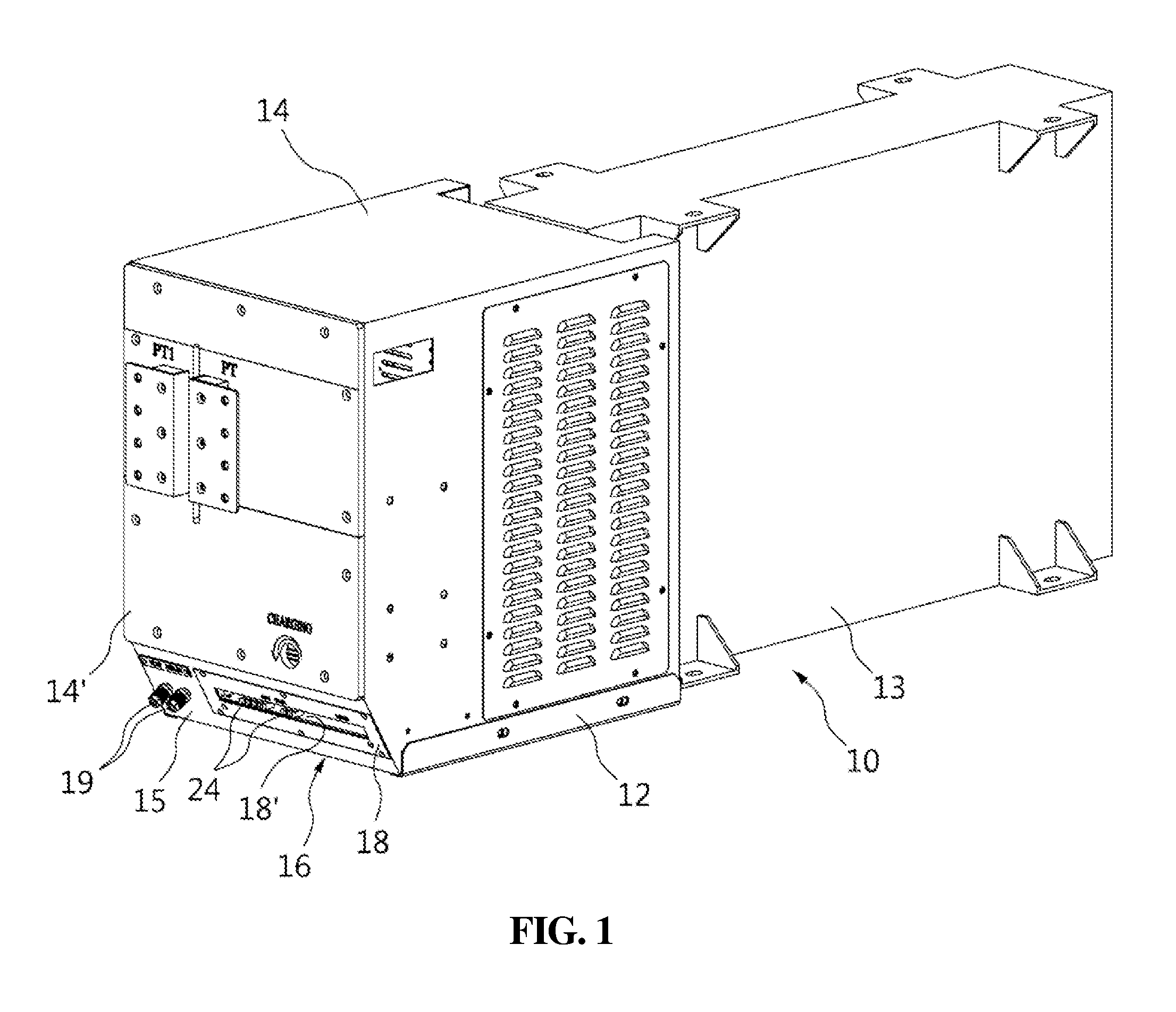
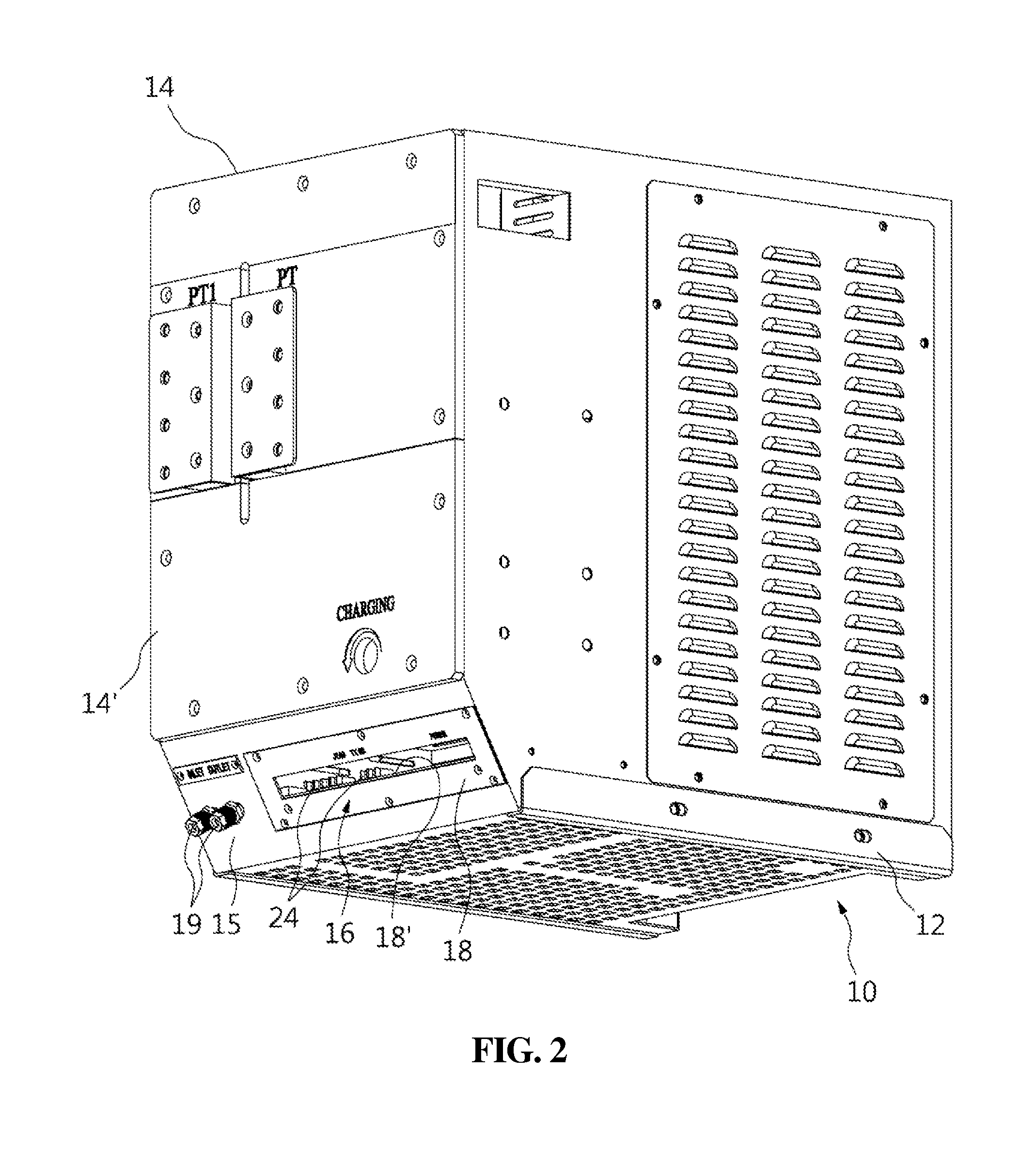
The modular apparatus for a high-voltage direct-current transmission system described in this patent aims to provide better visual inspection of modules, minimize influence from surroundings, and ensure stable signal connection between the module and the outside. More specifically, the invention includes an inclined surface at the front lower end of the power unit, a display unit on the inclined surface, and a control board connected to the display unit that can be moved into and out of the module. An optical cable is also used to connect the control board and a controller at the outside, ensuring a reliable signal connection.

Problems solved by technology

However, since the submodules are installed in a high structure, a worker has to use tools such as an aerial ladder, so it is difficult to check the states and maintain the control board.

Method used


Image

  • Modular apparatus for high voltage direct-current transmission system
  • Modular apparatus for high voltage direct-current transmission system
  • Modular apparatus for high voltage direct-current transmission system

Examples


Embodiment Construction

[0029]An embodiment of a modular apparatus for a high-voltage direct-current transmission system according to the present invention is described hereafter in detail with reference to the accompanying drawings. A submodule of modules for a high-voltage direct-current transmission system is exemplified herein.

[0030]As shown in the figures, a submodule 10 that is a modular apparatus of the present invention is largely composed of a power unit 12 and a capacitor unit 13. Various power semiconductors and various boards are in the power unit 12. A power unit housing 14 forms the external shape of the power unit 12. In this embodiment, the power unit housing 14 has a substantially hexahedral shape. The front 14′ of the power unit housing 14 is a flat surface with an inclined surface 15 at the lower end. The inclined surface 15 is formed by cutting off the edge between the front 14′ and the bottom of the power unit housing 14.

[0031]A display unit 16 is on the inclined surface 15. The displa...


PUM


Abstract

The present invention relates to a modular apparatus for a high-voltage direct-current transmission system. A sub-module (10), which is a modular apparatus, comprises according to the present invention a power unit (12) in the front and a capacitor unit (13) in the rear, and on the lower end of a front surface (14′) of a power unit housing (14) forming the exterior of the power unit (12) is a sloped surface (15). The sloped surface (15) has a hexahederal shape created by removing the edge formed by the front surface (14′) and the bottom surface of the power unit housing (14) and faces the ground at an angle. A display unit (16) is provided on the sloped surface (15) so that the status of the sub-module (10) can be easily checked by a worker from the ground on which a structure stands. A front panel (18) comprising the display unit (16) is provided on the sloped surface (15), wherein the front panel (18) is provided with a panel through-hole (18′) to allow a configuration space (20) in the interior to be visible. A control board (22) is coupled to the front panel (18) by means of a connection block (23). The control board (22) is movably supported on either end thereof by support rails (26) provided on both inner side walls of the configuration space (20) so as to allow easy entry into the interior and exit to the outside of the power unit (12).

Description

TECHNICAL FIELD[0001]The present invention relates to a modular apparatus for a high-voltage direct-current transmission system and, more particularly, to a modular apparatus for a high-voltage direct-current transmission system that allows for checking a modular apparatus, which is installed at a high position from the ground.BACKGROUND ART[0002]A HVDC (High Voltage Direct Current) system supplies power by converting AC power from a power plant into DC power, transmitting the DC power, and then inverting the DC power into AC power at a power receiving point. The HVDC system has a loss of power less than an AC transmission type, sot it has high power transmission efficiency. Further, the system can improve stability through line separation and has small inductive disturbance, so it is advantageous in long-distance power transmission.[0003]The HVDC system is installed in a structure called a converter module composed of a plurality of submodules stacked 10 meters high in a plurality ...

Claims


Application Information

Patent Timeline
Patent Type & Authority Applications(United States)
IPC IPC(8): H05K5/00H05K7/14H05K5/02H02J3/36
CPCH05K5/0017H05K5/0247H05K7/1427H02J3/36Y02E60/60H05K7/14339H05K5/0018H02M1/00H05K7/1432
Inventor KIM, JUNE-SUNGJUNG, HONG-JU
Owner HYOSUNG HEAVY IND CORP
Learn More