Electronic component mounting orientation checking system and electronic component mounting orientation checking method

a technology of electronic components and mounting orientation, applied in image data processing, instruments, image enhancement, etc., can solve problems such as the designated mounting position of electronic components, and achieve the effect of improving productivity

Active Publication Date: 2020-12-31
FUJI MASCH MFG CO LTD
View PDF0 Cites 0 Cited by
  • Summary
  • Abstract
  • Description
  • Claims
  • Application Information

AI Technical Summary

Benefits of technology

[0009]In this configuration, when the image of the mounting area on the circuit board and the representation of the electronic component are superimposed and displayed on the display device, the pad pattern orientation indicating portion, indicating the orientation of the pad pattern of the mounting area, and the component mounting orientation indicating portion, indicating the mounting orientation of the electronic component, are additionally displayed, the operator can easily visually check whether the mounting orientation of the electronic component designated in the production program is correct or reversed by 180° (or rotated by 90°, 180°, or 270° in a case of a square electronic component), by visually checking the pad pattern orientation indicating portion and the component mounting orientation indicating portion displayed on the display device. By this visual checking, in a case where the operator determines that the mounting orientation of the electronic component does not match the orientation of the pad pattern of the mounting area, the operator can edit the production program by operating the editing function section so that the mounting orientation of the electronic component matches the orientation of the pad pattern. Therefore, it is not necessary to perform test production for checking the mounting orientation of electronic component before the start of production, and it is possible to improve the productivity.

Problems solved by technology

In addition, there is a possibility that the mounting position of the electronic component designated in the production program may deviate from a position of a pad pattern of the actual circuit board used in production due to a production error or the like of the circuit board.

Method used


Image

  • Electronic component mounting orientation checking system and electronic component mounting orientation checking method
  • Electronic component mounting orientation checking system and electronic component mounting orientation checking method
  • Electronic component mounting orientation checking system and electronic component mounting orientation checking method

Examples


Embodiment Construction

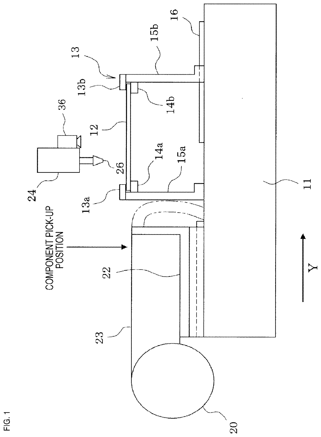
[0014]Hereinafter, an example will be described. First, a configuration of an electronic component mounter equipped with an electronic component mounting orientation checking system will be described with reference to FIG. 1.

[0015]Conveyor 13 for conveying circuit board 12 is provided on base table 11 of the electronic component mounter (hereinafter, a conveyance direction of circuit board 12 by conveyor 13 is defined as an X-direction, a direction perpendicular thereto is defined as a Y-direction). By fixing one support member 15a at a fixed position and adjusting a position of support member 15b in the Y-direction on a side opposite thereto along guide rail 16 by a feeding screw mechanism (not shown) or the like, among support members 15a and 15b which support two conveyor rails 13a and 13b, and conveyor belts 14a and 14b constituting conveyor 13, the width of conveyor 13 (interval between conveyor rails 13a and 13b) can be adjusted according to the width of circuit board 12.

[0016...


PUM


Abstract

A representation of the electronic component to be mounted according to a production program is displayed so as to be superimposed on the image of the mounting area on the display device, and the production program is edited so that a mounting orientation of the electronic component matches an orientation of the pad pattern, in a case where the mounting orientation of the electronic component designated in the production program does not match the orientation of the pad pattern in the mounting area when an operator looks at the representation of the electronic component displayed so as to be superimposed on the image of the mounting area on the display device.

Description

TECHNICAL FIELD[0001]The present specification discloses a technique relating to an electronic component mounting orientation checking system and an electronic component mounting orientation checking method, which check a mounting orientation of an electronic component to be mounted on a circuit board in accordance with a production program (production job) before starting the production.BACKGROUND ART[0002]As described in Patent Literature 1 (JP-A-2010-73958), an electronic component mounter for mounting an electronic component on a circuit board picks up multiple types of electronic components supplied from multiple feeders in an order designated by a production program and mounts the electronic component on a designated position of the circuit board. At this time, since not only the electronic components having the same mounting orientation, but also the electronic components having different mounting orientations are mixed in the electronic components to be mounted on the circui...

Claims


Application Information

Patent Timeline
Patent Type & Authority Applications(United States)
IPC IPC(8): G06T7/00H05K3/34
CPCG06T2207/30141G06T7/0004H05K3/3436H05K13/0882H05K13/0815
Inventor YOKOI, YUTAKOBAYASHI, TAKAHIROKITO, SHUICHIRO
Owner FUJI MASCH MFG CO LTD
Why Eureka
Try Eureka