Self-expansion of a layer 3 network fabric

a network fabric and layer 3 technology, applied in the field of self-expansion of layer 3 network fabric, can solve the problems of time-consuming and error-prone manual configuration of a new computing node in a leaf-spine network

Active Publication Date: 2019-01-17
NICIRA
View PDF6 Cites 11 Cited by
  • Summary
  • Abstract
  • Description
  • Claims
  • Application Information

AI Technical Summary

Benefits of technology

[0011]In some embodiments, configuring the L3 protocols comprises partitioning a subnet including the new computing node and one or more other computing nodes connected to the spine switches into one partition network for each computing node and creating one or more routes between the partition network of the new computing node and the partition networks of the one or more other computing nodes. In these embodiments, the subnet routes are used for transporting packets without Virtual Local Area Network (VLAN) tags between computing nodes.
[0012]In another embodiment, a system is provided having one or more computer readable storage media and a processing system operatively coupled with the one or more computer readable storage media. Program instructions stored on the one or more computer readable storage media, when read and executed by the processing system, direct the processing system to transfer one or more probe messages from each of the spine switches. The probe messages detect whether new computing nodes have been attached to the communication network. The program instructions further direct the processing system to receive a reply to at least one of the probe messages, wherein the reply identifies a new computing node that is not yet included in the L3 fabric. In response to the reply, the program instructions direct the processing system to confirm physical network interfaces of the spine switches indicate valid connections to one or more new leaf switches of the new computing node, use L3 discovery protocols to ensure the connections conform to the leaf-spine topology, and transfer probe packets between the spine switches and leaf switches, including the new leaf switches, of computing nodes connected thereto to confirm configuration of all connections between the spine switches and the leaf switches of the computing nodes. Also, the program instructions direct the processing system to configure L3 protocols for routing communications exchanged with the new computing node.

Problems solved by technology

As such, manual configuration of a new computing node in a leaf-spine network can be time consuming and error prone.

Method used


Image

  • Self-expansion of a layer 3 network fabric
  • Self-expansion of a layer 3 network fabric
  • Self-expansion of a layer 3 network fabric

Examples


Embodiment Construction

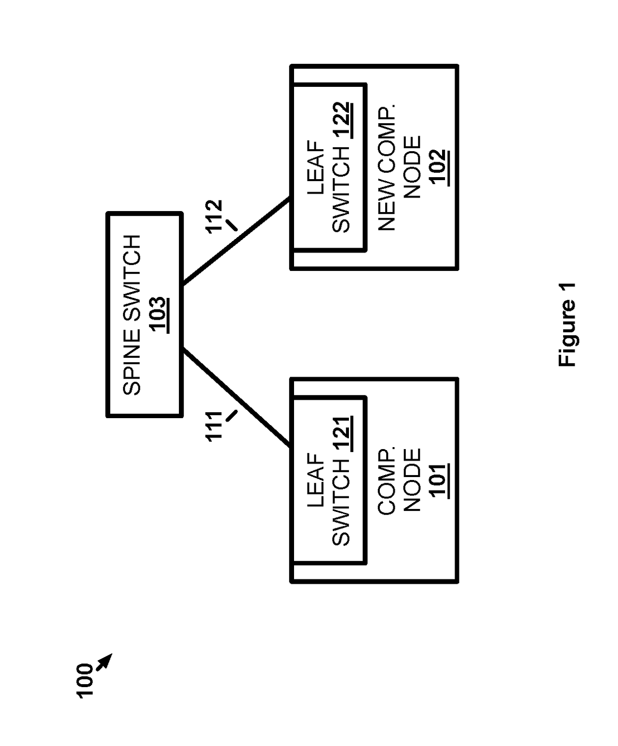
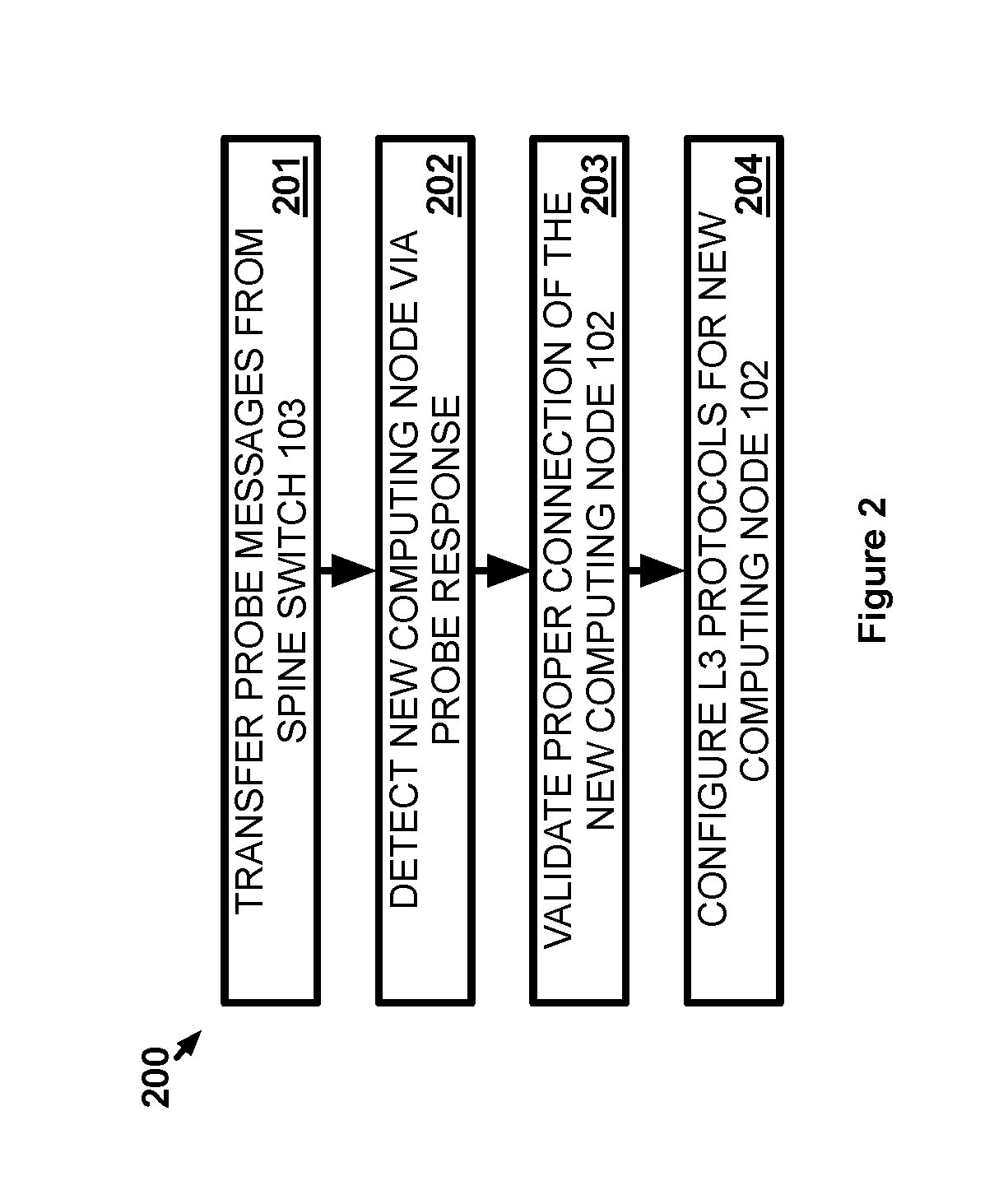
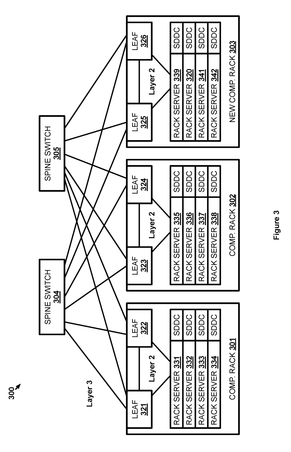
[0020]The implementations provided herein allow for the self-expansion of a leaf-spine L3 network fabric. The network topology of a leaf-spine network fabric includes L3 spine switches with L3 connections to leaf switches at computing nodes being networked by the leaf-spine network. Communications between the computing nodes are transferred through a spine switch via each computing node's leaf switches. One feature of the leaf-spine network topology is that communications between any two computing nodes need only traverse one of the spine switches in transit. The leaf-spine network topology therefore allows for the delay and latency for communications between any two computing nodes to be predictable and consistent across the entire leaf-spine network. With that in mind, any newly added computing node to the leaf-spine network must be connected and configured in a manner that conforms to the leaf-spine network topology. If the new computing node does not include the proper physical ...


PUM


Abstract

The technology disclosed herein enables an L3 network fabric including one or more spine switches having a leaf-spine topology to be self-expanded. In a particular embodiment, a method provides transferring one or more probe messages from each of the spine switches. The probe messages detect whether new computing nodes have been attached to the communication network. The method further provides receiving a reply to at least one of the probe messages. The reply identifies a new computing node that is not yet included in the L3 fabric. In response to the reply, the method provides confirming physical network interfaces of the spine switches indicate valid connections to one or more new leaf switches of the new computing node, using L3 discovery protocols to ensure the connections conform to the leaf-spine topology, and transferring probe packets between the spine switches and leaf switches, including the new leaf switches, of computing nodes connected thereto to confirm configuration of all connections between the spine switches and the leaf switches of the computing nodes. Moreover, the method provides configuring L3 protocols for routing communications exchanged with the new computing node.

Description

TECHNICAL BACKGROUND[0001]Leaf-spine network architecture uses spine switches to connect computing nodes, such as server racks, via leaf switches at those computing nodes. Each leaf switch is connected to each spine switch, which allows for consistency in communication delay and latency for communications between any two computing nodes. That is, communications from one communication node to another will always traverse only one spine switch when travelling between the leaf switches of those computing nodes. Dynamic Layer 3 (L3) routing may be used between the spine and leaf switches to account for dynamic network conditions. Since each spine switch is connected to each leaf switch, the dynamic L3 routing (e.g., Equal-Cost Multipath routing) may be used for load balancing communications being handled by any given switch.[0002]When a new computing node and its leaf switch(es) are added to an existing leaf-spine network, that computing node must first be connected properly to conform ...

Claims


Application Information

Patent Timeline
Patent Type & Authority Applications(United States)
IPC IPC(8): H04L12/751H04L12/933H04L12/24H04L45/02H04L45/24H04L45/74
CPCH04L45/02H04L49/10H04L41/12H04L49/1523H04L45/24H04L45/26H04L45/48H04L45/54H04L45/04H04L43/0817H04L45/033
Inventor KOMMULA, RAJAYAVATKAR, RAJENDRASRIDHAR, THAYUMANAVAN
Owner NICIRA
Why Eureka
Try Eureka