
Variable Viscosity Vaporizer Cartridge

Active Publication Date: 2019-01-24
ACROSS INFINITY LLC
View PDF8 Cites 23 Cited by
  • Summary
  • Abstract
  • Description
  • Claims
  • Application Information

AI Technical Summary

Benefits of technology

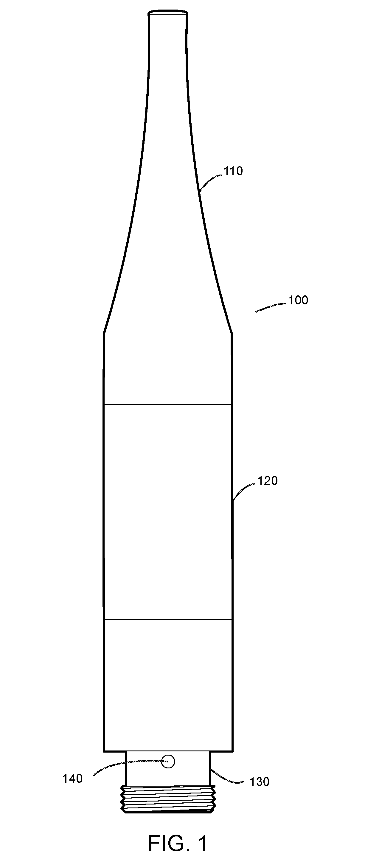
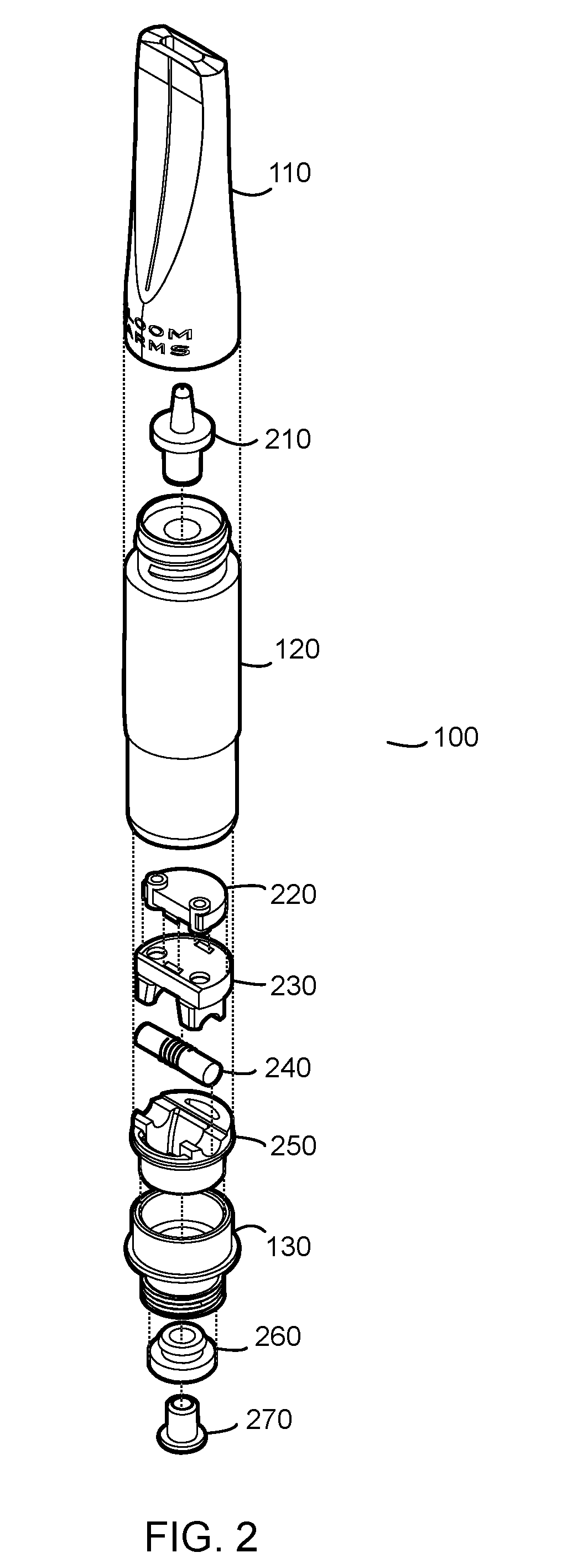
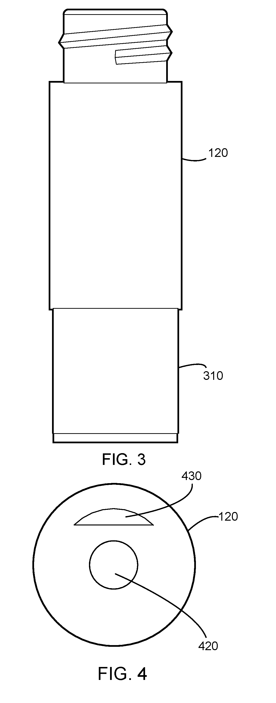
This patent addresses the problem of clogging in vaporizers caused by excess oil. The invention includes a residue basin in the vaporizer cartridge that collects any excess oil that is not vaporized during the first draw or inhalation. This prevents the excess oil from causing clogging. The residue basin is designed in close proximity to the wick so that the excess oil is vaporized during the next draw or inhalation, reducing waste and the potential for clogging. The invention also includes cross-draft across the wick created by configuring air intake vents and a vapor channel on opposite sides of the housing. This enhances the vaporization of the excess oil.

Problems solved by technology

Originally, the upper assembly was just silicone, but under variable temperature and pressure, the shape would deform and oil would leak down the side.
Originally tried a metal plate on top, that but didn't keep the structure and created a pressure issue.
However, this has the disadvantage that it allows to much oil to seep through to the wick, causing clogging.
However, such low viscosity oil tends to seep down through to the wick, and a higher viscosity oil is too thick to get down the holes.

Method used


Image

  • Variable Viscosity Vaporizer Cartridge
  • Variable Viscosity Vaporizer Cartridge
  • Variable Viscosity Vaporizer Cartridge

Examples


Embodiment Construction

[0042]Before the invention is described in further detail, it is to be understood that the invention is not limited to the particular embodiments described, as such may, of course, vary. It is also to be understood that the terminology used herein is for the purpose of describing particular embodiments only, and not intended to be limiting, since the scope of the present invention will be limited only by the appended claims.

[0043]Where a range of values is provided, it is understood that each intervening value, to the tenth of the unit of the lower limit unless the context clearly dictates otherwise, between the upper and lower limit of that range and any other stated or intervening value in that stated range is encompassed with the invention. The upper and lower limits of these smaller ranges may independently be included in the smaller ranges is also encompassed within the invention, subject to any specifically excluded limit in the stated range. Where the stated range includes on...


PUM


Abstract

A vaporizer and vaporizer cartridge for inhaling vapors from vaporized oil. The vaporizer has a mouthpiece for use by a user to inhale the vapors. The mouthpiece is connected to a cartridge which contains the oil to be vaporized and the apparatus for vaporizing the oil. The vaporizer cartridge contains a reservoir of the oil which flows down to a wick, which is heated by a heating coil to a temperature necessary to vaporize the oil. Under the wick is a residue basin which collects any oil which fails to vaporize. The residue basin is placed at an optimal distance from the wick such that when the next user initiates another draw on the vaporizer, the un-vaporized oil in the residue basin is vaporized. Below the cartridge is a battery component that provides power to a heating coil which heats the wick to vaporize the oil. Air flows up from below the cartridge on one side, then cross-flows across the wick and residue basin, and up the other side of the cartridge to the mouthpiece.

Description

CROSS-REFERENCE TO RELATED APPLICATIONS[0001]The present application claims the benefit of U.S. Provisional Application No. 62 / 534,684 filed on Jul. 20, 2017, incorporated by reference herein and for which benefit of the priority date is hereby claimed.FEDERALLY SPONSORED RESEARCH[0002]Not applicable.SEQUENCE LISTING OR PROGRAM[0003]Not applicable.FIELD OF INVENTION[0004]The present invention relates to a vaporizer, and more particularly to a vaporizer, cartomizer or cartridge which is configured to vaporize oils over a wide range of viscosities.BACKGROUND OF THE INVENTION[0005]Vaporizers are devices are used to vaporize an oil or other vaporizable material into a “vapor” for oral delivery to a user via inhalation. A vaporizer may include several elements, such as a power source, a reservoir containing the oil, and an atomizer to vaporize the oil. Vaporizers with an integrated atomizer and reservoir are referred to as a cartomizer. A vaporizer cartridge contains an integrated atomiz...

Claims


Application Information

Patent Timeline
IPC IPC(8): A61M16/14A61M16/10A61M15/00A61M15/06A24F40/10A24F40/44A24F40/485
CPCA61M16/145A61M16/109A61M15/0021A61M15/06A61M2205/3673A61M2205/8206A61M2205/0211A61M2205/3653A61M11/042A24F40/10A24F40/44A24F40/485A24F40/42
Inventor KOTCH, ERIC
Owner ACROSS INFINITY LLC
Learn More