Devices, systems, and methods for stimulation therapy

a technology of devices and systems, applied in the field of devices, systems and methods for stimulation therapy, can solve the problems of limiting the energy transfer efficiency, affecting the efficiency of energy transfer, and affecting the effect of suture retention

Active Publication Date: 2019-01-24
NEUSPERA MEDICAL INC
View PDF0 Cites 11 Cited by
  • Summary
  • Abstract
  • Description
  • Claims
  • Application Information

AI Technical Summary

Benefits of technology

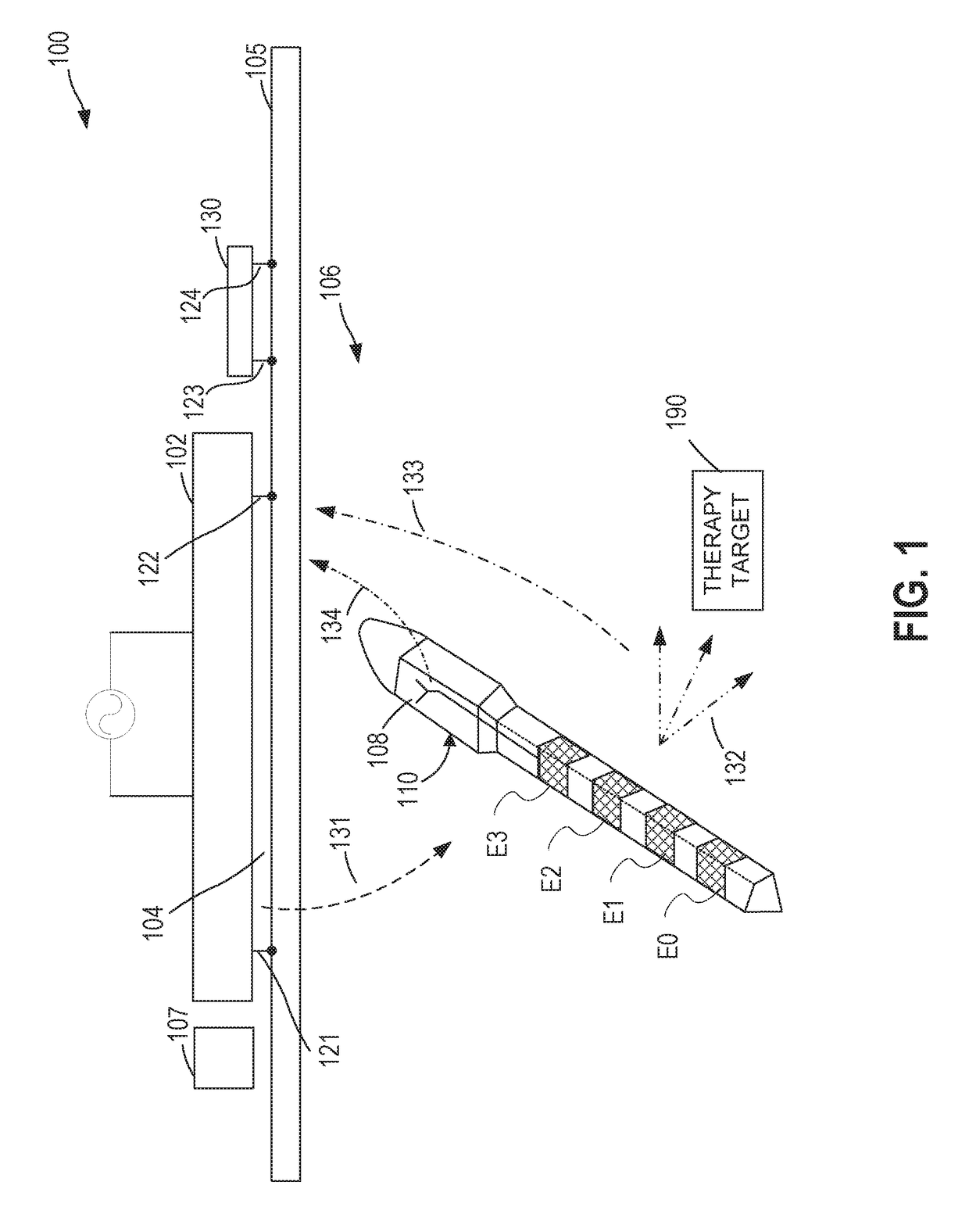
[0014]The circuitry of the internal therapy device may comprise a therapy delivery circuit configured to provide a phase-amplitude coupled therapy signal that includes a first signal component provided using a first neural electrostimulation vector and a second signal component provided using a different second neural electrostimulation vector, with the second signal component being provided substantially concurrently with the first signal component. In one embodiment, the at least partially implantable device comprises at least four electrodes that are axially spaced apart along a lead portion of the device, with two of the four electrodes being configured for use as the first neural electrostimulation vector and the other two of the four electrodes being configured for use as the second neural electrostimulation vector. In some embodiments, the therapy delivery circuit is configured to adjust an amplitude or frequency characteristic of at least one of the first and second signal components of the phase-amplitude coupled therapy signal to overcome a patient's neural pathophysiology or to otherwise improve neurologic function (e.g., to overcome symptoms, such as related to one or more of a body movement disorder, Parkinson's disease, dementia, Alzheimer's disease, Creutzfeldt-Jakob disease, Huntington's disease, depression (e.g., by stimulating a left cervical vagus nerve or trigeminal nerve), dystonia, or epilepsy, among others). Improved neurologic function can include improved cognitive and / or motor function.
[0018]In some embodiments, the system can include one or more mechanisms for implanting / explanting the implantable device from a body. In such embodiments, the implantable device can include a connection structure in a proximal portion thereof that is configured to mate with a mating connection structure of a pushrod. The pushrod can be a hollow element, in some embodiments, such as to include a hole longitudinally therethrough. The pushrod can be used to position the implantable device inside the body. The implantable device can include a suture attached thereto, such as at a location more proximal than the antenna housing and / or deployment tines. The hole in the pushrod can be configured such that the pushrod can slide down the suture with the suture situated in the hole. In one or more embodiments, a second pushrod can be configured to be inserted (e.g., next to the suture) in the hole and contact the connection of the implantable device, such as to allow the pushrod to be separated from the implantable device. In some embodiments, the pushrod can be configured to help secure the suture in place, such as to help prevent the suture from slipping in and / or out of a body it is placed in. In such embodiments, the pushrod can include a female luer thread and the system can further comprise a male luer cap configured to be mated with female luer thread. The male luer cap can include a hole therethrough that is configured to be situated over the suture, such that when the male luer cap is mated with the female luer thread, the male luer cap presses on the suture, such as to help retain the position of the suture.
[0082]In some embodiments, generating the self-interference mitigation signal is based on calculated or measured information about a signal leakage between respective pairs of the multiple RF ports of the midfield transceiver device. The method may further comprise providing the power and / or data signal from the midfield transceiver device, using the multiple RF ports, to the implantable device, wherein the power and / or data signal is based on an RF carrier signal, and wherein the generating the self-interference mitigation signal comprises providing an amplitude-modulated and / or phase-modulated version of the RF carrier signal. The method may further comprise determining a quality characteristic of the extracted information signal from the backscatter signal and, based on the quality characteristic, selectively updating the self-interference mitigation signal to enhance the quality.

Problems solved by technology

Most of the known wireless powering methods for implantable electronics are based on the nearfield coupling method, and these and other suggested methods suffer from a number of disadvantages.
The coils external to the body in near-field coupling methods are also typically bulky and inflexible.
This presents difficulties with regard to the incorporation of the external device into daily life.
On the other hand, the radiative nature of the far field severely limits the energy transfer efficiency.

Method used


Image

  • Devices, systems, and methods for stimulation therapy
  • Devices, systems, and methods for stimulation therapy
  • Devices, systems, and methods for stimulation therapy

Examples


Embodiment Construction

[0301]Midfield powering technology can provide power to a deeply implanted electrostimulation device from an external power source located on or near a tissue surface, such as at an external surface of a user's skin. The user can be a clinical patient or other user. The midfield powering technology can have one or more advantages over implantable pulse generators. For example, a pulse generator can have one or more relatively large, implanted batteries and / or one or more lead systems. Midfield devices, in contrast, can include relatively small battery cells that can be configured to receive and store relatively small amounts of power. A midfield device can include one or more electrodes integrated in a unitary implantable package. Thus, in some examples, a midfield-powered device can provide a simpler implant procedure over other conventional devices, which can lead to a lower cost and a lower risk of infection or other implant complications. One or more of the advantages can be fro...


PUM


Abstract

Generally discussed herein are systems, devices, and methods for providing a therapy (e.g., stimulation) and / or data signal using an implantable device. Systems, devices and methods for interacting with (e.g., communicating with, receiving power from) an external device are also provided.

Description

RELATED APPLICATIONS[0001]This application claims priority benefit to the following U.S. provisional applications: U.S. Provisional Application No. 62 / 244,495 filed Oct. 21, 2015 and titled “COMPACT INTEGRATION OF ELECTRONIC CONTROL HARDWARE WITH ELECTROMAGNETIC TRANSMITTING ELEMENT”; U.S. Provisional Application No. 62 / 264,239 filed Dec. 7, 2015 and titled “DISCREET EXTERNAL DEVICE COUPLING TO IMPLANTED DEVICE”; U.S. Provisional Application No. 62 / 291,379 filed Feb. 4, 2016 and titled “IMPLANTABLE STIMULATION DEVICES AND STEERING AND AFFIXING MECHANISMS THEREFORE”; U.S. Provisional Application No. 62 / 350,674 filed Jun. 15, 2016 and titled “WIRELESS NEURAL THERAPY DELIVERY SYSTEMS AND METHODS USING A SERIES OF ELECTROSTIMULATION SIGNALS”: U.S. Provisional Application No. 62 / 350,676 filed Jun. 15, 2016 and titled “IMPLANTABLE STIMULATION DEVICES AND STEERING MECHANISMS THEREFORE”; U.S. Provisional Application No. 62 / 350,681 filed Jun. 15, 2016 and titled “IMPLANTABLE STIMULATION DEVI...

Claims


Application Information

Patent Timeline
Patent Type & Authority Applications(United States)
IPC IPC(8): A61N1/36A61N1/05A61N1/372H02J50/10H02J50/40A61N1/375
CPCA61N1/36062A61N1/0551A61N1/36185A61N1/37223A61N1/37247H02J50/10H02J50/40A61N1/37252A61N1/3756A61N1/37518A61N1/3787H02J50/90H02J50/80H02J7/00034H02J50/20A61B5/00A61N1/37229A61N1/0558H02J2310/23
Inventor FAYRAM, TIMOTHY A.YEH, ALEXANDERSHAW, GARYARMSTRONG, RANDOLPH KERRYMORRIS, MILTON M.JUNCO, ELIA
Owner NEUSPERA MEDICAL INC
Why Eureka
Try Eureka