Handle for sports or work equipment and equipment comprising the handle

a technology for sports or work equipment and handles, applied in the field of handles for sports equipment, can solve the problems of inability to use, difficulty in ensuring the stability of the whole racquet, and difficulty in ensuring the stability of the whole racquet, and achieve the effect of maximum comfort and maximum adhesion

Active Publication Date: 2019-01-24
GEREMIA GIANLUCA
View PDF4 Cites 6 Cited by
  • Summary
  • Abstract
  • Description
  • Claims
  • Application Information

AI Technical Summary

Benefits of technology

[0042]A particular object is to provide a handle for sports or work equipment that allows to hold the equipment always in a firm manner a

Problems solved by technology

These solutions provide for a modification of the rod structure of the frame and therefore they are not usable by users already in possession of the racquet, but they may be inserted only in the production stage of a new tool.
Then, having to modify the structure of the frame implies

Method used


Image

  • Handle for sports or work equipment and equipment comprising the handle
  • Handle for sports or work equipment and equipment comprising the handle
  • Handle for sports or work equipment and equipment comprising the handle

Examples


first embodiment

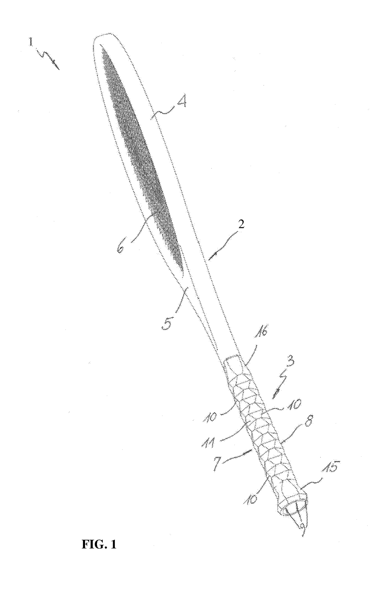
[0080]FIG. 1 shows the sport equipment 1 from which it is noted that the handle 3 essentially comprises a tubular body 7 which extends along a longitudinal axis L and which has an outer peripheral surface 8 adapted to be grasped by a user.

[0081]The outer peripheral surface 8 is shaped with a plurality of longitudinal faces 9 in side by side relationship with each other each having a plurality of edges 10 which extend along the longitudinal axis L to facilitate the positioning of the finger joints of the gripping hand by the user.

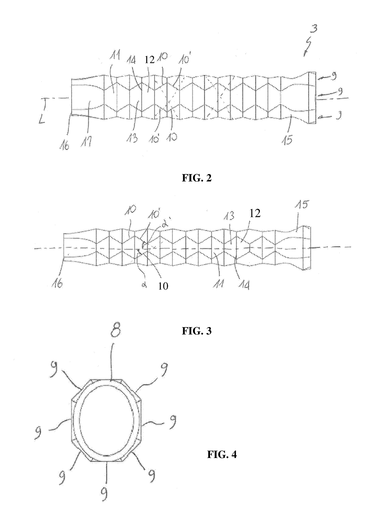
[0082]As it can be seen more clearly from FIGS. 2 and 3, the edges 10 are arranged along at least one pair of helical or spiral paths, shown with dashed lines, which develop around the longitudinal axis L with opposite sign.

[0083]In this way each of the longitudinal faces 9 will be divided into a plurality of areas or flat surfaces 11 longitudinally aligned and dimensioned so that in the multiple mode of gripping the handle 3 they may accommodate a correspon...

second embodiment

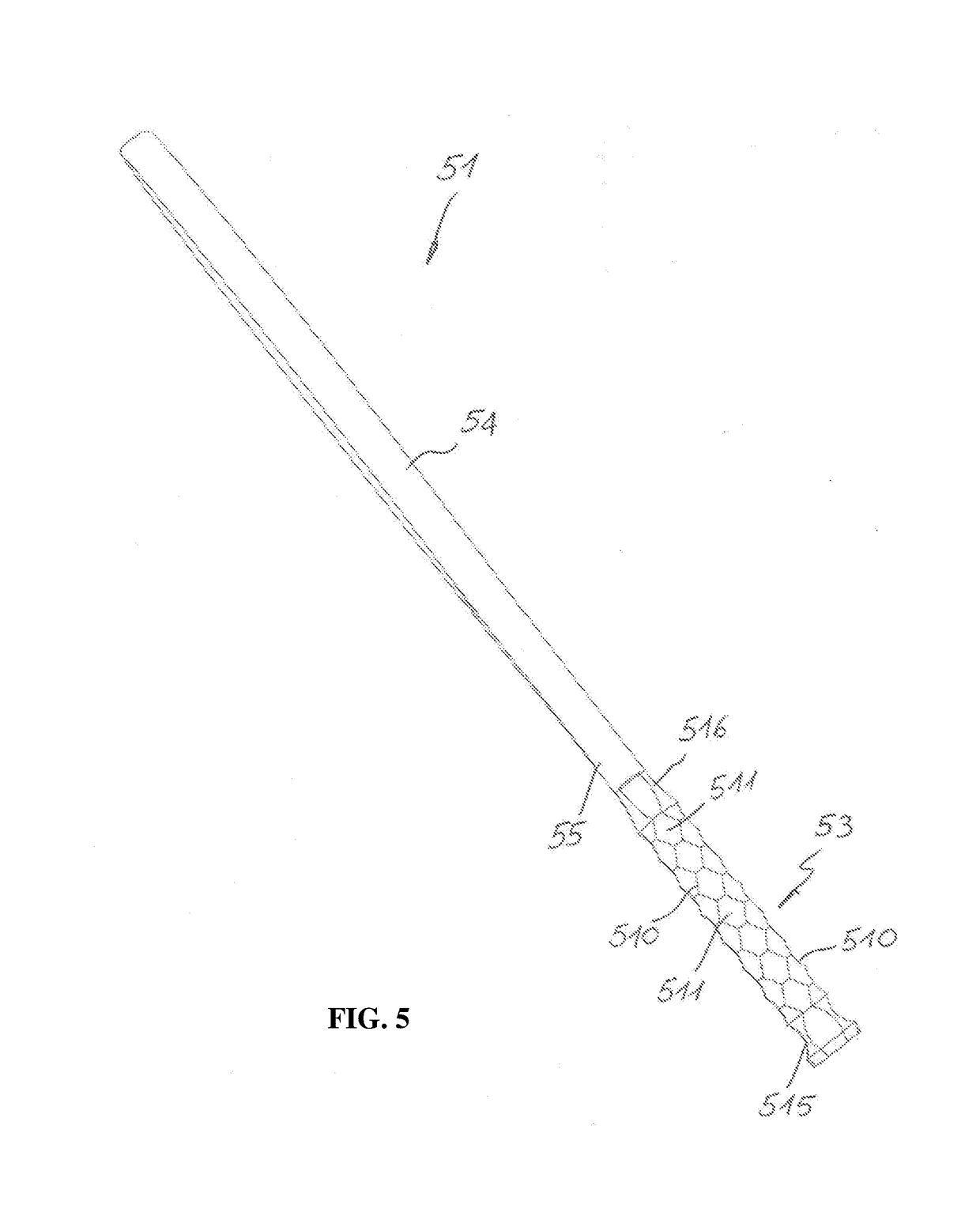
[0100]FIG. 5 shows the handle 53 that differs from the previous essentially by the fact that the areas or flat surfaces 511, in which the longitudinal faces 59 are divided, are concave.

[0101]In addition, the edges 510 are not perfectly straight but slightly curved, in particular concave, so as to better accommodate the anatomy of the hand and to ensure greater comfort.

[0102]In the embodiment of FIG. 8 the areas or flat surfaces 811 have plan shape substantially similar to those of the embodiment of FIG. 1 but they are internally drilled to define a honeycomb structure.

[0103]The tubular body 87 also comprises one or more longitudinal aeration channels 818 open at the ends and which extend along respective longitudinal rows of faces, so as to promote the circulation of air and counteract the sweating of the hand.

[0104]The channels 818 are parallel to the longitudinal axis L of the handle 3 and may extend to the whole or just part of the longitudinal extension of the perimeter surface ...


PUM


Abstract

A handle for sport equipment comprises a tubular body (7) which extends along a longitudinal axis (L) and has an outer peripheral surface (8) adapted to be grasped by a user and shaped with a plurality of longitudinal faces (9) placed side by side in correspondence of edges (10) adapted to facilitate the positioning of the finger joints of the gripping hand by the user. The edges (10) are arranged along at least one pair of helical or spiral paths that develop around said longitudinal axis (L) with mutually opposite sign to subdivide each of said longitudinal faces (9) into a plurality of areas or flat surfaces (11) sized to accommodate a corresponding phalanx of the gripping hand of the user, each of said areas or flat surfaces (11) being perimetrically delimited by at least one pair of edges (10, 10′) of each of the helical or spiral paths.

Description

TECHNICAL FIELD[0001]The present invention relates to the technical field of sports equipment and has for object a handle for sports equipment, applicable in particular to sports equipment designed to hit a ball, such as tennis racquets and the like, or to work equipment equipped with handles. The invention also relates to an equipment comprising the handle.STATE OF THE ART[0002]The racquet sports, such as tennis, beach tennis, badminton, paddle, squash and the like, involve the use of an equipment, generally called racquet, composed of a head, i.e. the equipment portion designed to hit the ball, and of a handle designed for grabbing the equipment and which the hand rests on to control the equipment itself.[0003]Many racquets also comprise a throat, arranged between the head and the handle of the racquets.[0004]The handle of the racquet generally comprises a shell or two specular half-shells, named pallets, assembled by means of an adhesive and firmly fastened to a rod which, togeth...

Claims


Application Information

Patent Timeline
IPC IPC(8): A63B60/12A63B49/08A63B53/14A63B60/08A63B60/18
CPCA63B60/12A63B49/08A63B53/14A63B60/08A63B60/18A63B2102/02A63B2102/04A63B2102/065A63B2102/16A63B2102/18A63B59/50A63B60/48A63B2102/06A63B60/52A63B59/42B25G1/102
Inventor GEREMIA, GIANLUCA
Owner GEREMIA GIANLUCA
Why Eureka
Try Eureka