Conductive roll

Active Publication Date: 2019-01-24
NOK CORP +2
View PDF0 Cites 0 Cited by
  • Summary
  • Abstract
  • Description
  • Claims
  • Application Information

AI Technical Summary

Benefits of technology

[0017]According to the present invention, there can be provided a conductive roller that can ensure uniform image density. The unifo

Problems solved by technology

However, since in recent years image-forming apparatuses provide high-quality images at low current, generation of image unevenness cannot be prevented merely by c

Method used


Image

  • Conductive roll

Examples


Example

Example 1

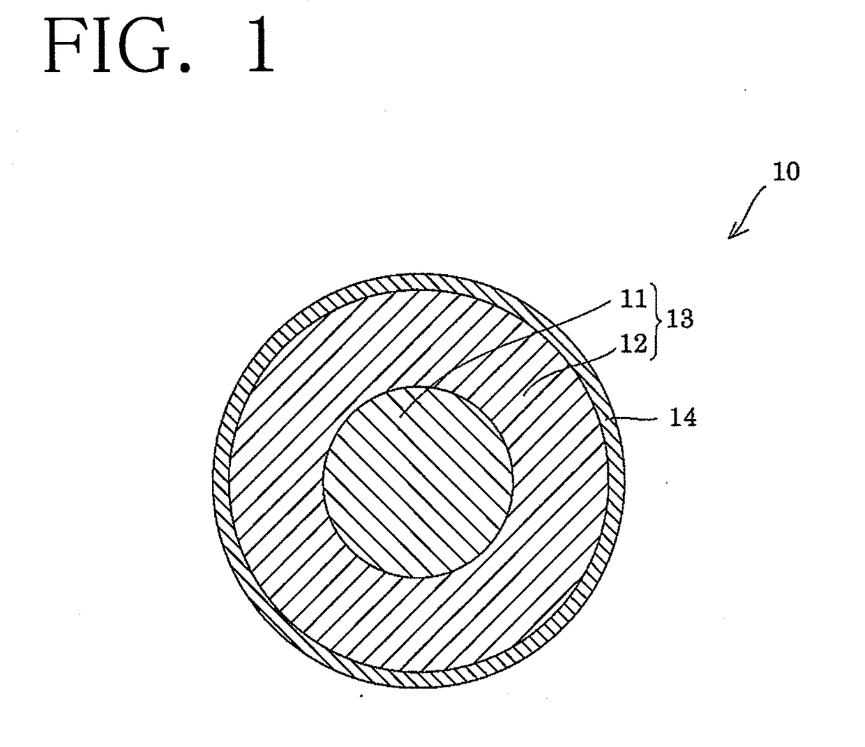
[0055]In Example 1, sodium trifluoroacetate (conductivity-imparting agent) (0.5 parts by mass), zinc flower (3 parts by mass), stearic acid (2 parts by mass), and a vulcanizing agent (1.5 parts by mass) were added to epichlorohydrin rubber (Epichlomer CG-102; product of Daiso Co., Ltd.) (100 parts by mass), and the mixture was kneaded by means of a roller mixer. The kneaded product was press-formed onto the surface of a metallic core (diameter: 8 mm), to thereby yield a roller substrate having, on the surface of the metallic core, an elastic layer formed of a vulcanized epichlorohydrin rubber. In Example 1, the hardness of the elastic layer of the thus-produced roller substrate was measured by means of a type-A durometer (“JIS K 6253”). The measured hardness was about 45° to about 65°.

[0056]Next, a coating liquid for forming a coating layer on the roller substrate was prepared. In a specific procedure, a base material, conducting agents 1 to 3, and a solvent for dilution sh...

Example

Examples 2 and 3

[0072]In Examples 2 and 3, the procedure of Example 1 was repeated, except that the amount of the surface roughness-imparting agent in the coating liquid was changed, whereby charge rollers were produced (see Table 1), surface roughness was measured with respect to roller substrates and charge rollers (see Table 2), and image uniformity (unevenness in image density) was assessed with respect to each charge roller, which was set in an actual printer (see Table 3).

Example

[0073]In Examples 4 to 6, the procedure of Example 3 was repeated, except that the dilution solvent for the coating liquid was changed, whereby charge rollers were produced (see Table 1), surface roughness was measured with respect to roller substrates and charge rollers (see Table 2), and image uniformity (unevenness in image density) was assessed with respect to each charge roller, which was set in an actual printer (see Table 3).


PUM


Abstract

This conductive roll includes: at least one elastic layer 12 including primarily a conductive rubber body and provided along the outer periphery of a core 11; and a coating layer 14 provided along the outer periphery of the elastic layer 12. The conductive roll satisfies the following expressions: circumference Sm1≤135 μm and circumference Sm1<circumference Sm2 wherein circumference Sm1 represents an average interval Sm of irregularities along the circumferential direction of the elastic layer 12, and circumference Sm2 represents an average interval Sm of irregularities along the circumferential direction of the coating layer 14.

Description

TECHNICAL FIELD[0001]The present invention relates to a conductive roller employed in image-forming apparatuses including an electrophotographic copying machine or printer, and a toner-jet-type copying machine or printer. More particularly, the invention relates to a charge roller to be employed for uniformly imparting electric charge to a photoreceptor or the like of an image-forming apparatus.BACKGROUND ART[0002]Generally known image-forming apparatuses include an electrophotographic copying machine or printer, and a toner-jet-type copying machine or printer. Such an image-forming apparatus generally includes a photoreceptor (e.g., a photoreceptor drum), which generates electric charge upon light exposure. In addition to the photoreceptor, the image-forming apparatus has a plurality of conductive members including conductive rollers such as a development roller, a charge roller, a transfer roller, and a toner-supplying roller, and a conductive belt such as a transfer belt.[0003]On...

Claims


Application Information

Patent Timeline
IPC IPC(8): G03G15/02F16C13/00
CPCG03G15/0233F16C13/00G03G15/00G03G15/02G03G15/08G03G15/16G03G15/0216
Inventor OURA, KOUSUKEOGURA, HIROSHITAHARA, MASAKI
Owner NOK CORP
Why Eureka
Try Eureka