Microphone Mount For A Speaker Cabinet

a microphone and speaker cabinet technology, applied in the direction of transducer casings/cabinets/supports, loudspeakers, frequency/directions obtaining arrangements, etc., can solve the problems of degrading sound quality, easy knocking out of place, and affecting the performance of performers, so as to hinder the rotation of the adjustable foot, the effect of preventing unwanted sonic rumble and extra stability

Inactive Publication Date: 2019-01-24
DUCKER MAXWELL PHILIP
View PDF7 Cites 3 Cited by
  • Summary
  • Abstract
  • Description
  • Claims
  • Application Information

AI Technical Summary

Benefits of technology

[0012]The adjustable foot that traverses the channel strip preferably has two 90 degree folds that run either side of the out outer edges of the body, allowing extra stability and hindering rotation of the adjustable foot. Preferably, the adjustable foot includes a material that lines the surface of the adjustable foot that comes into contact with the loudspeaker cabinet. The material

Problems solved by technology

Tripods and other microphone stands utilize legs or weighted bases that can present hazards to performers and are easily knocked out of place when performers need access to their loudspeaker or ampli

Method used


Image

  • Microphone Mount For A Speaker Cabinet
  • Microphone Mount For A Speaker Cabinet
  • Microphone Mount For A Speaker Cabinet

Examples


Embodiment Construction

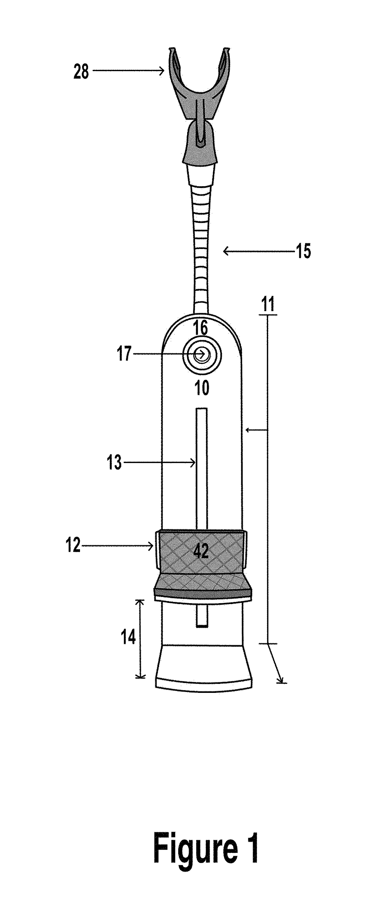
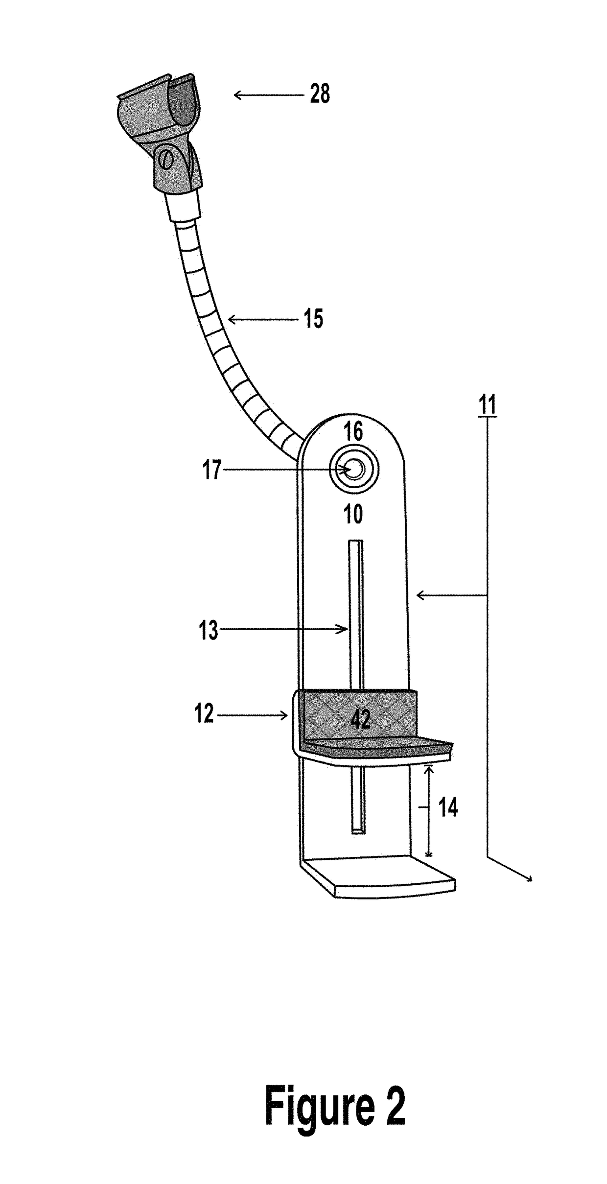
[0033]An apparatus 10 according to the present invention will now be described with reference to the drawings. With reference to FIG. 1 and FIG. 2, the apparatus 10 includes an “L” shaped body 11 with a separate adjustable foot 12 that slides in a longitudinal motion along a channel strip 13 to bridge a desired distance 14 between the loudspeaker cabinet [NOT SHOWN] and an opposing surface [NOT SHOWN] to achieve a wedge and secure mount. A positioning arm 15 is attached to the body 11 and is used to position the microphone housing 28 and microphone to a desired distance from a loudspeaker. The positioning arm 15 is fixed to the top inside face 16 of the body 11 with a fastener 17. A piece of resilient material 42 with high memory properties lines the contact area of the adjustable foot 12 to achieve a secure mount and minimize sonic artifacts inherently generated by the loudspeaker or floor that apparatus 10 is in contact with.

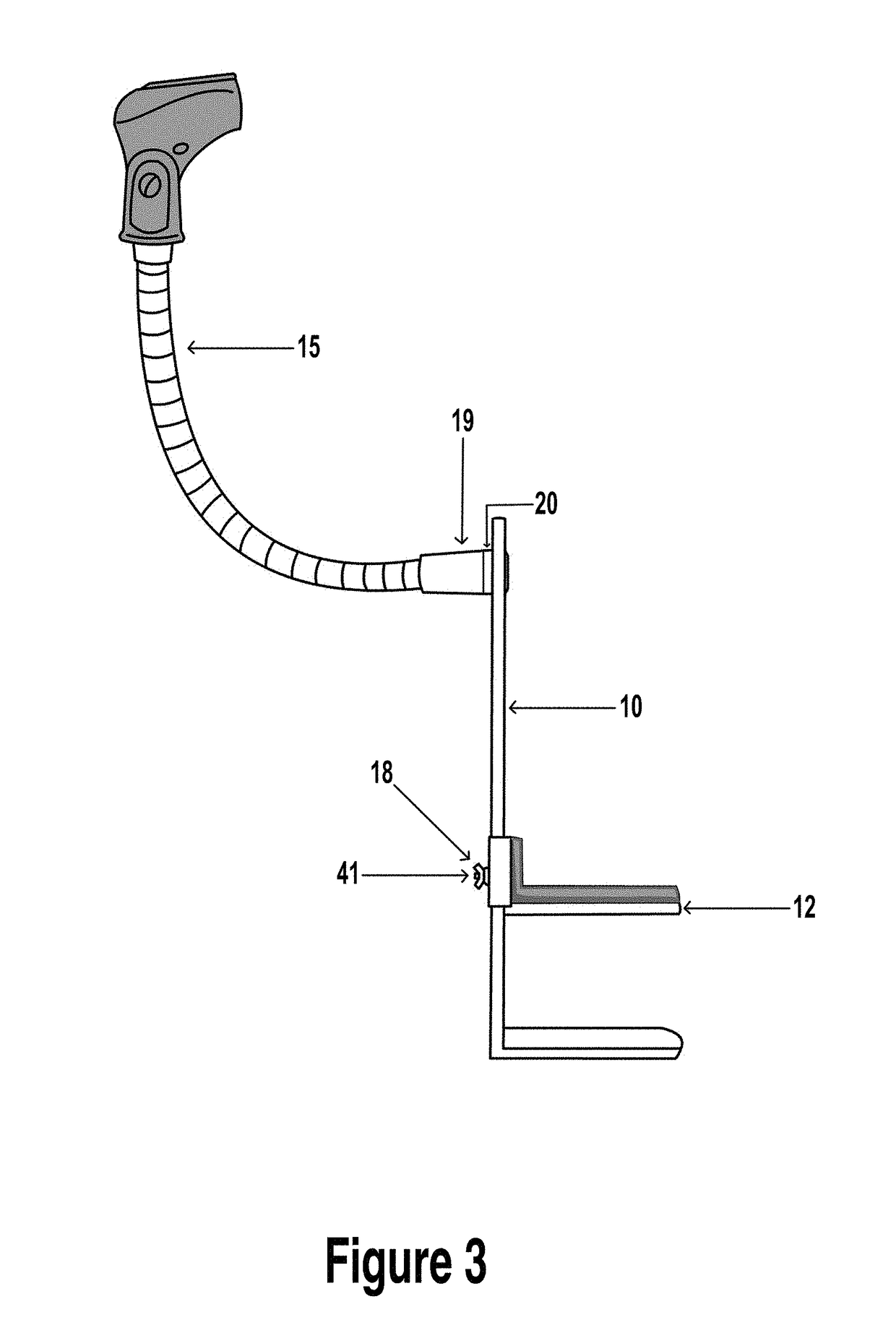
[0034]FIG. 3 is a side view of the apparatus 10 and furt...


PUM


Abstract

A microphone apparatus for mounting a microphone adjacent to a loudspeaker housed in a loudspeaker cabinet is defined by, an “L” shaped body with an adjustable foot that slides in a longitudinal direction along a channel strip to bridge a desired distance between the speaker cabinet and an opposing surface to achieve a wedge and secure mount. A positioning arm is fixed to the face of the “L” shape body and used to position the microphone to the desired distance of the loud speaker in the loudspeaker cabinet.

Description

FIELD OF THE INVENTION[0001]This invention relates to devices used by Sound engineers, Production companies and musicians to mount microphones to other equipment, more specifically to an apparatus for mounting a microphone to a loudspeaker cabinet.BACKGROUND OF THE INVENTION[0002]Sound engineers, musicians and others involved in the music industry often use microphones to amplify sound from loud speakers. With a multitude of varying sized loudspeaker cabinets and microphones available, typically a microphone is held in a clip attached to a tripod stand. The tripod is generally positioned on the floor in front of the loudspeaker cabinet and angled to the desired distance from of the loudspeaker.[0003]Tripods and other microphone stands utilize legs or weighted bases that can present hazards to performers and are easily knocked out of place when performers need access to their loudspeaker or amplifier or during a performance for example. Either loudspeaker accessibility or cramped per...

Claims


Application Information

Patent Timeline
IPC IPC(8): H04R1/08H04R1/32
CPCH04R1/326H04R1/083H04R1/02H04R1/08H04R2201/025
Inventor DUCKER, MAXWELL PHILIP
Owner DUCKER MAXWELL PHILIP
Why Eureka
Try Eureka