Disassembler for iron sleeve of drag arm

a technology of disassembly and drag arm, which is applied in the direction of transportation and packaging, vehicle components, manufacturing tools, etc., can solve the problems of difficult disassembly of iron sleeve and high manpower consumption of iron sleeve, and achieve the effect of preventing damage to iron sleeve and drag arm bushing, and increasing practicality

Active Publication Date: 2019-01-31
SIANG TOOLS DEV
View PDF0 Cites 7 Cited by
  • Summary
  • Abstract
  • Description
  • Claims
  • Application Information

AI Technical Summary

Benefits of technology

[0004]In view of the above-mentioned problems, the object of the present invention is to provide a disassembler for an iron sleeve of a drag arm which can change a diameter of a casing for clamping a bushing according to the size of the bushing and can detach the iron sleeve from the bushing of the drag aim in a simple and gradual way so as to achieve efficacy of time-saving, effort-saving, and increased practicality and to prevent damages to the iron sleeve and the bushing of the drag arm.

Problems solved by technology

Traditional methods and disassembler structures of disassembling an iron sleeve from a bushing of a drag arm by beating the iron sleeve usually consume lots of manpower.
Furthermore, if the applied pounding force is deviated from the center of the iron sleeve, the iron sleeve and the bushing are prone to deformation and damage which make the iron sleeve difficult to disassemble.

Method used


Image

  • Disassembler for iron sleeve of drag arm
  • Disassembler for iron sleeve of drag arm
  • Disassembler for iron sleeve of drag arm

Examples


Embodiment Construction

[0032]Hereinafter, an exemplary embodiment of the present invention will be described in detail with reference to the accompanying drawings.

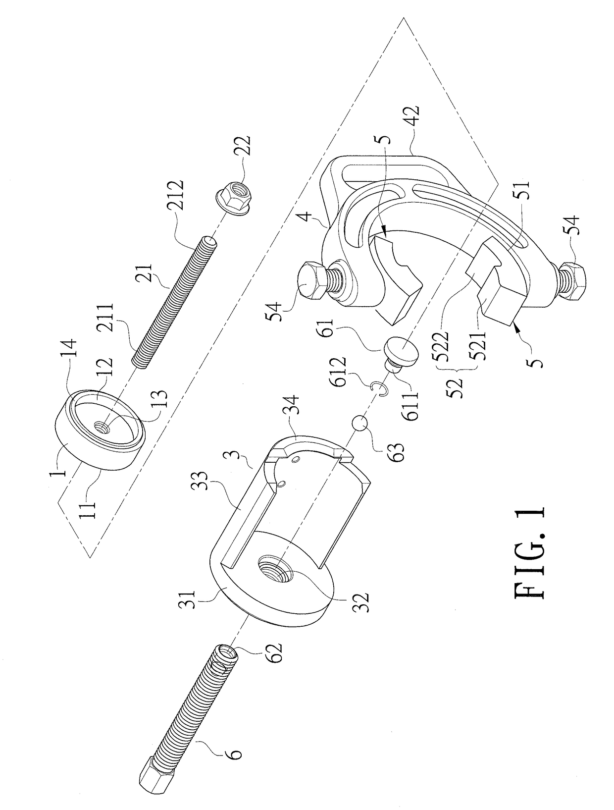
[0033]As showed in FIGS. 1-4, disassembler for an iron sleeve of a drag arm is disclosed. It comprises a top push casing (1), a first screw (21), a bolt nut (22), a casing (3), a clamping seat (4), two positioning elements (5), and a second screw (6).

[0034]The top push casing (1) has a closed end (11), an open end (12) opposite to the closed end (11), and a first threaded hole (13) disposed at the closed end (11). The open end (12) of the top push casing (1) is provided with a rim (14) for jointing the iron sleeve (30) in a bushing (20) of a drag arm.

[0035]The first screw (21) has a first end (211) for screwing into the first threaded hole (13) and a second end (212) opposite to the first end (211). The second end (212) of the first screw (21) is inserted into the iron sleeve (30) of a drag arm and further screwed into the bolt nut (22) for posi...


PUM


Abstract

A disassembler for an iron sleeve of a drag arm is disclosed. It comprises a top push casing, a bolt nut, a first screw inserted into an iron sleeve of a drag arm and screwed on the top push casing and the bolt nut, a casing for accommodating a bushing, a clamping seat, two positioning elements disposed on the clamping seat for clamping the casing and the bushing and for positioning the casing on the bushing, and a second screw screwed on the casing and contacting the top push casing in the bushing.

Description

BACKGROUND OF THE INVENTION1. Field of the Invention[0001]The present invention relates to a disassembler for an iron sleeve of a drag arm which can disassemble iron sleeves from drag arms.2. Description of Related Art[0002]Traditional methods and disassembler structures of disassembling an iron sleeve from a bushing of a drag arm by beating the iron sleeve usually consume lots of manpower. Furthermore, if the applied pounding force is deviated from the center of the iron sleeve, the iron sleeve and the bushing are prone to deformation and damage which make the iron sleeve difficult to disassemble.[0003]Accordingly, it is imperative to improve the traditional structures for disassembling iron sleeves from bushings of drag arms to meet the demand for effort-saving and having increased convenience.SUMMARY OF THE INVENTION[0004]In view of the above-mentioned problems, the object of the present invention is to provide a disassembler for an iron sleeve of a drag arm which can change a di...

Claims


Application Information

Patent Timeline
Patent Type & Authority Applications(United States)
IPC IPC(8): B25B27/28
CPCB60G2204/41B25B27/28B25B27/062
Inventor HUANG, SHENG-PIN
Owner SIANG TOOLS DEV
Why Eureka
Try Eureka