Three-dimensional printing device and method for printing three-dimensional object

a three-dimensional object and printing device technology, applied in the direction of manufacturing enclosures, additive manufacturing processes, applying layer means, etc., can solve the problems of increasing the consumption and waste of powder materials, requiring large amount of labor to prepare for printing and processing, and reducing the amount of powder materials needed for printing. , the effect of reducing the amount of powder materials

Inactive Publication Date: 2019-01-31
ROLAND DG CORP
View PDF0 Cites 5 Cited by
  • Summary
  • Abstract
  • Description
  • Claims
  • Application Information

AI Technical Summary

Benefits of technology

[0009]According to the three-dimensional printing device and a method for printing a three-dimensional object described in the preceding paragraphs, a powder layer including a flat portion smaller than the printing table as seen in a plan view is able to be formed. Thus, the powder layer may be formed on one region of the printing table, not on the entirety of the printing table. This eliminates the wasteful formation of the powder layer even on a region, on the printing table, where the three-dimensional object is not to be formed, and the amount of the powder material needed for the printing is able to be decreased.

Problems solved by technology

In the case where a large amount of powder material is used, a large amount of labor is needed to prepare for the printing and to perform processing after the printing.
In addition, an uncured portion of the powder material is not all reusable, which increases the consumption and waste of the powder material.

Method used


Image

  • Three-dimensional printing device and method for printing three-dimensional object
  • Three-dimensional printing device and method for printing three-dimensional object
  • Three-dimensional printing device and method for printing three-dimensional object

Examples


embodiment 1

Preferred Embodiment 1

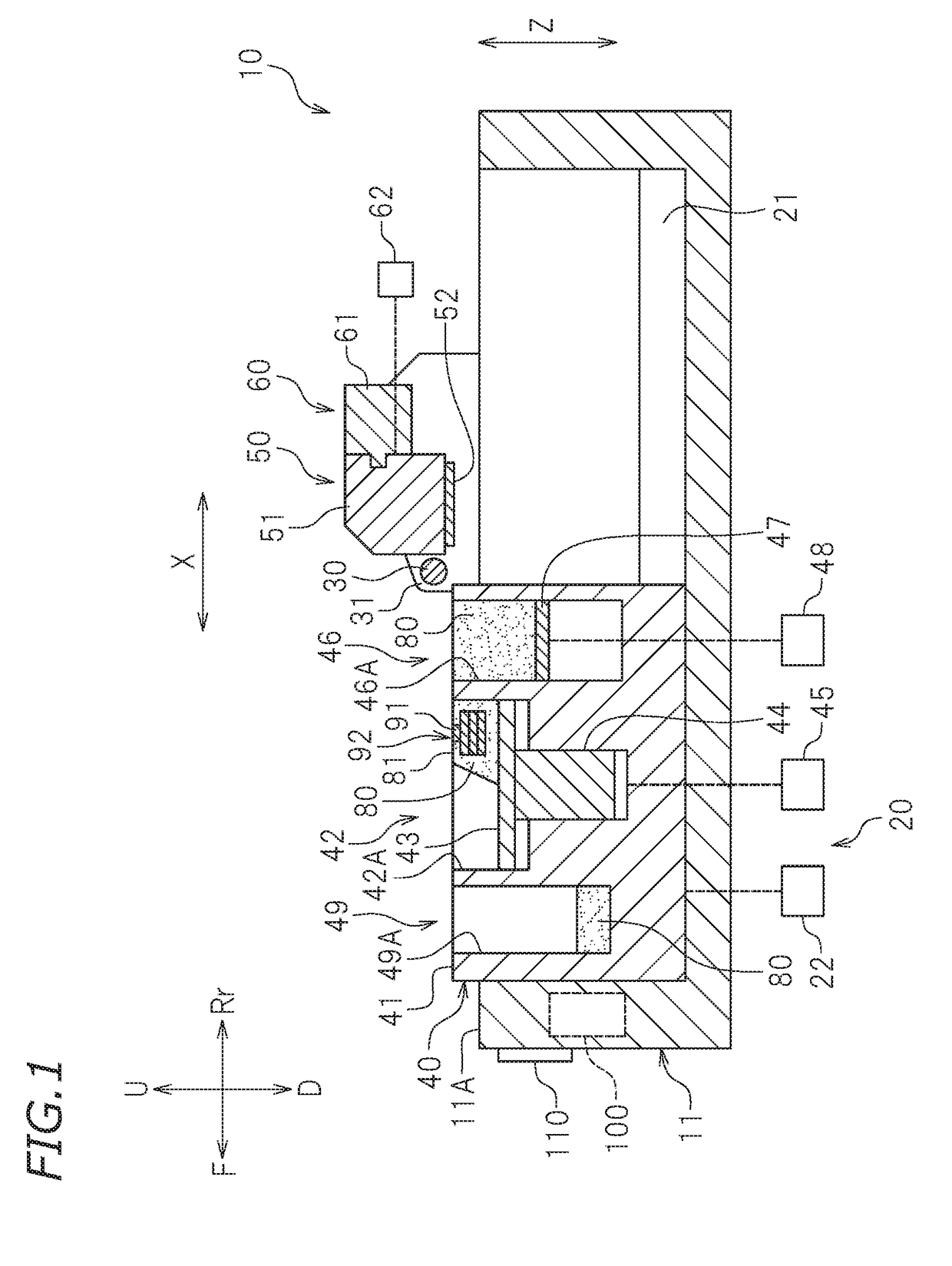
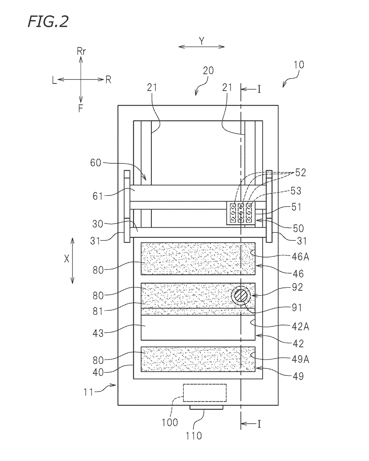
[0023]FIG. 1 is a cross-sectional view of a three-dimensional printing device 10 according to preferred embodiment 1. FIG. 2 is a plan view of the three-dimensional printing device 10 in this preferred embodiment. The cross-sectional view in FIG. 1 is taken along line I-I in FIG. 2. In FIG. 1, letter F represents “forward”, and letter Rr represent “rearward”. In this preferred embodiment, the terms “left”, “right”, “up” and “down” represent left, right, up and down as seen from a person who faces a front surface of the three-dimensional printing device 10. In the drawings, letters L, R, U and D respectively represent left, right, up and down. In this preferred embodiment, letters X, Y and Z respectively represent a front-rear direction, a left-right direction, and an up-down direction. The left-right direction Y is a scanning direction of the three-dimensional printing device 10. The front-rear direction X is a feeding direction of the three-dimensional printin...

embodiment 2

Preferred Embodiment 2

[0065]In preferred embodiment 2, the length of the formation region of the powder layer 81 is designated also in the scanning direction Y. This preferred embodiment is the same as preferred embodiment 1 except for this point. In the description of this preferred embodiment, elements that are the same as those in preferred embodiment 1 will bear the identical reference signs thereto, and overlapping descriptions will be omitted or simplified.

[0066]FIG. 6 is a schematic cross-sectional view of a three-dimensional printing device 10 in this preferred embodiment. As shown in FIG. 6, the three-dimensional printing device 10 in this preferred embodiment includes neither the supply tank 46 nor the members related thereto (bottom 47, supply tank elevator 48) shown in FIG. 1 or FIG. 2 but includes a powder supply member 70. The powder supply member 70 drops and thus supplies the powder material 80 onto the printing table 43 from above.

[0067]As shown in FIG. 6, the powde...

embodiment 3

Preferred Embodiment 3

[0077]In preferred embodiment 3 of the present invention, the formation region of the powder layer 81 is automatically set based on the printing data on the three-dimensional object 92 stored on the data storage 101. In the description of this preferred embodiment also, elements that are the same as those in preferred embodiments 1 and 2 will bear the identical reference signs thereto, and overlapping descriptions will be omitted or simplified.

[0078]FIG. 9 is a block diagram of a three-dimensional printing device10 in this preferred embodiment. In this preferred embodiment, the controller 100 does not include the region input 103 but includes a curing region computation processor 104C in the supply amount setter 104. A supply amount computation processor 104D has different specifications from those of the supply amount computation processor 104A in preferred embodiment 1 or the supply amount computation processor 104B in preferred embodiment 2.

[0079]The curing ...


PUM

PropertyMeasurementUnit
thicknessaaaaaaaaaa
heightaaaaaaaaaa
sizeaaaaaaaaaa

Abstract

A three-dimensional printing device includes a layer former that levels off a supplied powder material to form a powder layer including a flat portion having a predetermined height on a printing table, and a supply amount setter that sets an amount of the powder material to be supplied. The supply amount setter sets, as the amount of the powder material to be supplied, an amount smaller than a reference supply amount corresponding to a volume determined as a result of an area size of the printing table being multiplied by the predetermined height. If an amount smaller than the reference supply amount is set as the amount of the powder material to be supplied, the layer former forms the powder layer having the flat portion such that the flat portion has an area size smaller than the area size of the printing table.

Description

CROSS REFERENCE TO RELATED APPLICATION[0001]This application claims the benefit of priority to Japanese Patent Application No. 2017-146096 filed on Jul. 28, 2017. The entire contents of this application are hereby incorporated herein by reference.BACKGROUND OF THE INVENTION1. Field of the Invention[0002]The present invention relates to a three-dimensional printing device and a method for printing a three-dimensional object.2. Description of the Related Art[0003]Conventionally, a powder stack method of ejecting a binder toward a powder material and curing the powder material to print a desired three-dimensional object is disclosed in Japanese Patent No. 5400042.[0004]A three-dimensional printing device disclosed in Japanese Patent No. 5400042 includes a printer portion accommodating powder, a powder supplier accommodating the powder to be supplied to the printer portion, and an inkjet head located above the printer portion. The inkjet head ejects aqueous ink toward the powder accommo...

Claims


Application Information

Patent Timeline
Patent Type & Authority Applications(United States)
IPC IPC(8): B29C64/165B33Y70/00B29C64/255B33Y10/00
CPCB29C64/165B33Y70/00B29C64/255B33Y10/00B33Y30/00B33Y50/02B29C64/209B29C64/393
Inventor IWASE, FUMIYOSHI
Owner ROLAND DG CORP
Why Eureka
Try Eureka