Conveyance Device Using Carriage

a technology of conveying device and carriage, which is applied in the direction of mechanical conveyors, rope railways, vehicles, etc., can solve the problems of difficult to reliably fit the driven pin of the conveying carriage, varied time delay, and time delay, and achieves the effect of convenient and reliable fitting, simple structure and inexpensive implementation

Active Publication Date: 2019-01-31
DAIFUKU CO LTD
View PDF5 Cites 4 Cited by
  • Summary
  • Abstract
  • Description
  • Claims
  • Application Information

AI Technical Summary

Benefits of technology

[0005]In the configuration of the present invention described above, the positioning of the conveyance carriage at the fixed position by the carriage positioning means is released and simultaneously, the carriage pushing-out means is operated such that the conveyance carriage which is stopped at the fixed position is forcibly fed out from the storage route part to the downstream side drive route part, therefore, a required time after a point in time at which the carriage pushing-out means is operated until the driven pins of the conveyance carriage reach the inside of the turning route of the carriage propulsion claw parts is determined by the pushing-out speed of the carriage pushing-out means, with the result that the required time is substantially constant although such required time is an extremely short period of time. Therefore, at a point in time at which the carriage propulsion claw parts reach a fixed position by a distance corresponding to the required time in front thereof from a position at which the carriage propulsion claw parts of the drive route part intersect the entrance route of the driven pins of the conveyance carriage, the positioning of the conveyance carriage at the fixed position is released and simultaneously, the carriage pushing-out means is operated, with the result that the driven pins of the conveyance carriage fed out toward the drive route part can be pushed into the carriage propulsion claw parts of the drive route part so as to be reliably fitted thereinto. As described above, in the configuration of the present invention, the conveyance carriage which is temporarily stopped within the storage route part is fed into the downstream side drive route part and is synchronized with the carriage propulsion claw parts of the drive route part, and thus the conveyance carriage can be driven to travel in the drive route part. As a matter of course, the travel interval between the conveyance carriages in the downstream side drive route part can also be freely set.
[0006]Although in a case where the present invention is implemented, the carriage positioning means can also be formed with a combination of a front stopper which receives the conveyance carriage at the fixed position and a rear anti-back stopper which allows the passage of the conveyance carriage but which automatically returns after the passage, in this configuration, the interval between the front stopper and the rear anti-back stopper is longer than the length of a portion sandwiched between both the front and rear stoppers on the side of the conveyance carriage, with the result that play in the forward / backward direction of the conveyance carriage positioned at the fixed position is enlarged. By contrast, the carriage positioning means is formed with a stopper (32) which freely switches between an action position for restraining the forward movement of the conveyance carriage (3) and a non-action position for allowing the forward movement of the conveyance carriage (3), and a pusher (44) which pushes the conveyance carriage (3) from the rear so as to position the conveyance carriage (3) between the pusher (44) and the stopper (32) in the action position, with the result that the play in the forward / backward direction of the conveyance carriage positioned at the fixed position can be substantially eliminated. Therefore, the stopper for restraining the forward movement of the conveyance carriage is switched to the non-action position and simultaneously, the carriage pushing-out means is operated, and thus the timing at which the conveyance carriage is pushed out is made to match the timing at which the carriage pushing-out means is operated, with the result that the driven pins of the conveyance carriage fed out from the storage route part can be more reliably fitted into the carriage propulsion claw parts of the downstream side drive route part.
[0007]In a case where the pusher (44) as described above is used together in the carriage positioning means, the pusher (44) is formed such that the pusher (44) can be moved forward from a first forward limit position (P1) for positioning the conveyance carriage (3) at the fixed position between the pusher (44) and the stopper (32) in the action position to a second forward limit position (P2) for pushing out the conveyance carriage (3) from the fixed position in a state where the stopper (32) is switched to the non-action position, and thus the pusher (44) can be made to also serve as the carriage pushing-out means (34). In this configuration, by only making one pusher perform a two-stage operation, the pusher can be made to serve both as the pusher for the carriage positioning means and the pusher for the carriage pushing-out means, and one to-be-pressed portion can be made to serve as to-be-pressed portions necessary for the side of the conveyance carriage, with the result that the structure is made simple such that the present embodiment can be implemented inexpensively.
[0008]Although the stopper can also be formed with one stopper for receiving the center portion of the conveyance carriage in the left / right width direction, it is preferable that a pair of left and right stoppers (32) are provided to receive two left and right portions on the rear end side of the conveyance carriage (3). In this configuration, the conveyance carriage can be stopped so as to be accurately directed toward the front, it is therefore possible to smoothly perform the subsequent transfer of the conveyance carriage to the drive route part. In this case, in each of the wheels (21a, 21b) respectively provided as left and right pairs in two front and rear portions of the conveyance carriage (3), pins (22a, 22b) are provided so as to protrude outward and concentrically, pins (22a) which are provided so as to protrude from the pair of left and right wheels (21a) on the front side can be used as the driven pins, and pins (22b) which are provided so as to protrude from the pair of left and right wheels (21b) on the rear side can be used as targets with which the pair of left and right stoppers (32) are engaged. As a matter of course, an auxiliary stopper (31) which receives a center portion in the left / right width direction of the conveyance carriage (3) on the front end side can also be provided separately from the pair of left and right stoppers. With the auxiliary stopper, it is possible to obtain an effect as a safety measure when the operation of the pair of left and right stoppers on the rear side becomes unstable, and furthermore, the auxiliary stopper can be switched to the action position before the pair of left and right stoppers on the rear side to stop the conveyance carriage, and thereafter the pair of left and right stoppers on the rear side can be switched to the action position and thus it is possible to position the conveyance carriage at the fixed position without the conveyance carriage colliding against the pair of left and right stoppers on the rear side.

Problems solved by technology

However, in actuality, the conveyance carriage which becomes free starts to move as the drive conveyor chain supporting the conveyance carriage via the roller moves, and thus, there is a time delay after the release of the stopper until the start of the movement of the conveyance carriage at rest, a time delay until the conveyance carriage reaches a predetermined speed, and the like, and the time delay is varied even by the weight of a conveyed object loaded on the conveyance carriage.
Therefore, it is very difficult to reliably fit the driven pin of the conveyance carriage into the carriage propulsion claw part which turns at a constant speed.

Method used


Image

  • Conveyance Device Using Carriage
  • Conveyance Device Using Carriage
  • Conveyance Device Using Carriage

Examples


Embodiment Construction

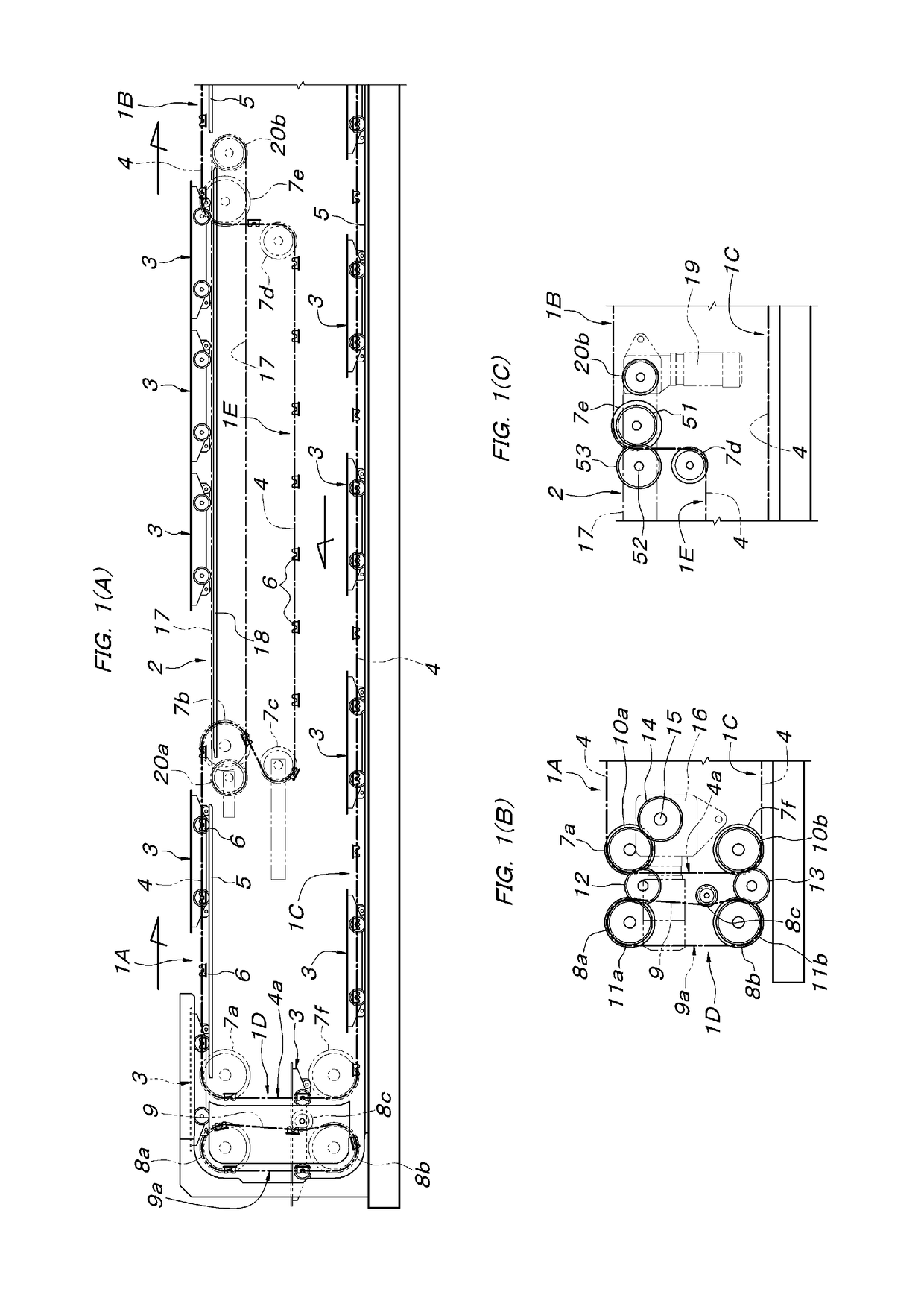
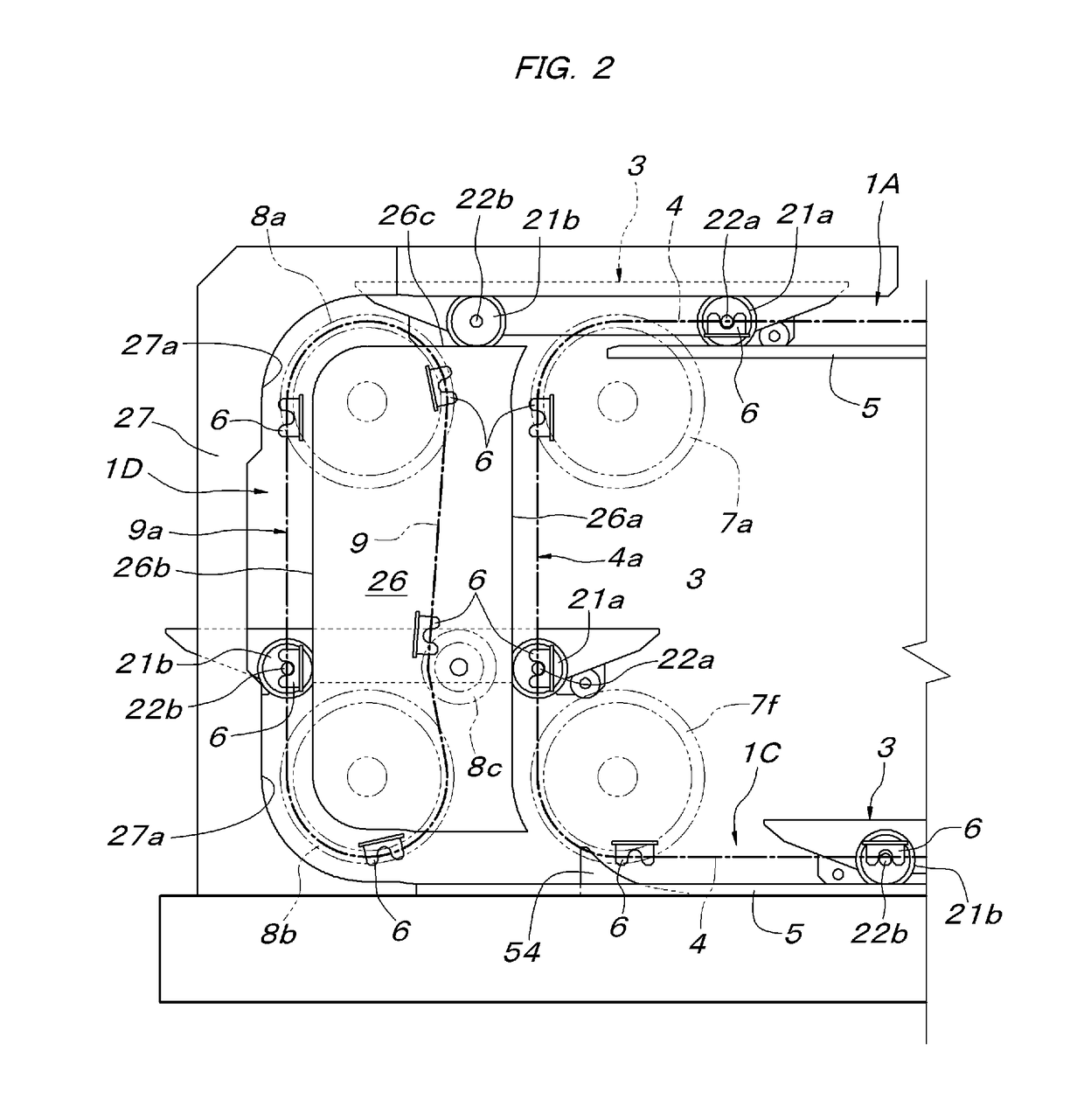
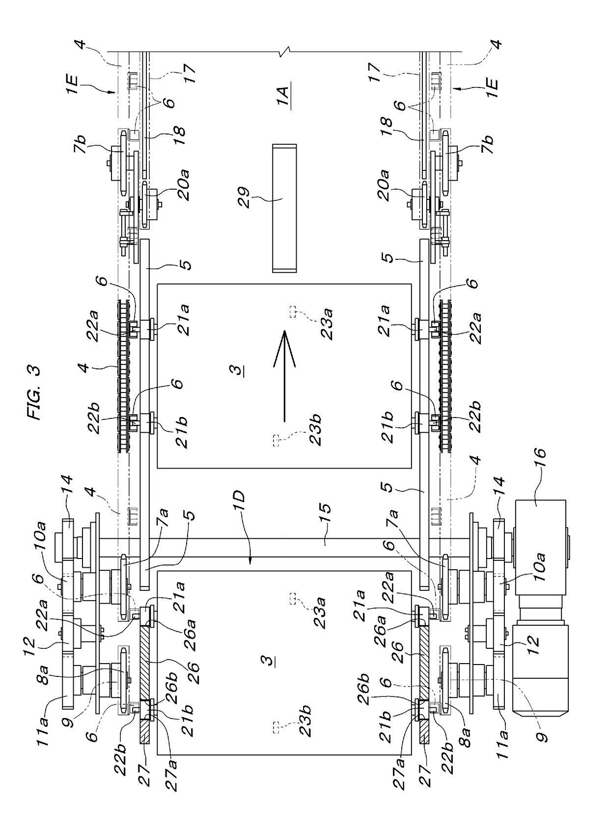
[0022]An embodiment of the present invention will be described below with reference to accompanying drawings. In FIGS. 1 to 4, reference sign 1A denotes an upstream side drive route part, reference sign 1B denotes a downstream side drive route part, and reference sign 2 denotes a storage route part arranged horizontally between the upstream side drive route part 1A and the downstream side drive route part 1B, and a horizontal conveyance route of a conveyance carriage 3 is formed with the upstream side drive route part 1A, the storage route part 2, and the downstream side drive route part 1B that are horizontally continuous. Reference sign 10 denotes a return drive route part, communicates with the downstream side of the downstream side drive route part 1B and is arranged horizontally directly below the upstream side drive route part 1A and the storage route part 2. The return drive route part 10 is connected via a rising route part 1D to the beginning end portion of the upstream sid...


PUM


Abstract

A conveyance device has a drive route part wherein conveyance carriages travel at predetermined intervals, which is connected to a storage route part having a drive conveyer chain that supports the conveyance carriages for free travel. The drive route part has a drive conveyer chain including spaced carriage propulsion claw parts. The conveyance carriages have moved pins that horizontally extends in the left / right direction and which are freely detached / re-fitted in the up / down direction with the carriage propulsion claw parts. The conveyance device has a carriage-positioning mechanism which positions a conveyance carriage at a fixed position wherein the moved pin is positioned immediately before a guide ring for a corresponding one of the carriage propulsion claw parts, and has a carriage pushing-out mechanism which pushes out the conveyance carriage positioned at the fixed position, at a timing when the moved pin is fitted to the carriage propulsion claw part.

Description

FIELD OF THE INVENTION[0001]The present invention relates to a conveyance device using a carriage which includes a horizontal travel route of a conveyance carriage that supports and conveys a conveyed object.BACKGROUND OF THE INVENTION[0002]As this type of conveyance device, a conveyance device in which a storage route part for storing (temporarily stopping) a conveyance carriage and a drive route part for causing the conveyance carriage fed out from the storage route part to be forcibly driven to travel at set intervals are provided has been known in, for example, Japanese Published Unexamined Patent Application No. 2011-79624 (Patent Literature 1), etc. In the configuration disclosed in Japanese Published Unexamined Patent Application No. 2011-79624 described above, the storage route part is formed with a drive conveyor chain which includes a roller for supporting the conveyance carriage such that the conveyance carriage freely travels, and a stopper which receives and stops the c...

Claims


Application Information

Patent Timeline
Patent Type & Authority Applications(United States)
IPC IPC(8): B65G35/06
CPCB65G35/06B61B10/00B65G17/002B65G17/123B65G17/14
Inventor ISHIBASHI, MASAHIROTAMURA, YUKICHIKUSUHARA, SHIGEYUKIBABA, SHIGERU
Owner DAIFUKU CO LTD
Why Eureka
Try Eureka