Bearing assembly unit and motor

a bearing assembly and motor technology, applied in the direction of bearing unit rigid support, shaft assembly, mechanical apparatus, etc., can solve the problems of difficult materialization of a stable turning operation, deterioration of the adhesion strength between the sleeve and the bearing element, and likely affect of adhesive properties, etc., to achieve stable turning operation and stable turning operation

Active Publication Date: 2019-01-31
SANKYO SEIKI MFG CO LTD
View PDF11 Cites 2 Cited by
  • Summary
  • Abstract
  • Description
  • Claims
  • Application Information

AI Technical Summary

Benefits of technology

[0015]As described above, in the case of the bearing assembly unit according to the disclosure; it becomes possible to materialize a stable turning operation even under environment of high temperature. Furthermore, in the case of the motor according to the disclosure; it becomes possible to prevent the rolling bearing element from rolling together so as to maintain a stable turning operation even under environment of high temperature, so that it becomes possible to lead to a long motor life.

Problems solved by technology

Unfortunately, characteristics of the adhesive are likely affected by thermal condition.
Therefore, in the case where the bearing assembly unit described above is used in the motor that is expected to operate under environment of high temperature above 100 degrees Celsius; for example, such as an in-car motor; heat generated by the motor itself also affects so that adhesion strength between the sleeve and the bearing element may sometimes deteriorate.
As a result of that, it becomes difficult to prevent the inner ring and the outer ring of the bearing element from rolling together, so that there exists a problem that it is difficult to materialize a stable turning operation under environment of high temperature.
Furthermore, in the case of the motor provided with the bearing assembly unit, described above, it becomes difficult because of generation of a vibration, a noise, and the like, to make the motor stably turn, in such a way that a life of the motor decreases.
With the issue described above being taken into consideration, it is an issue of the disclosure to provide a bearing assembly unit, a motor and an assembling method of the bearing assembly unit that materialize a stable turning operation even under environment of high temperature, so as to lead to a long component life.

Method used


Image

  • Bearing assembly unit and motor
  • Bearing assembly unit and motor
  • Bearing assembly unit and motor

Examples


first embodiment

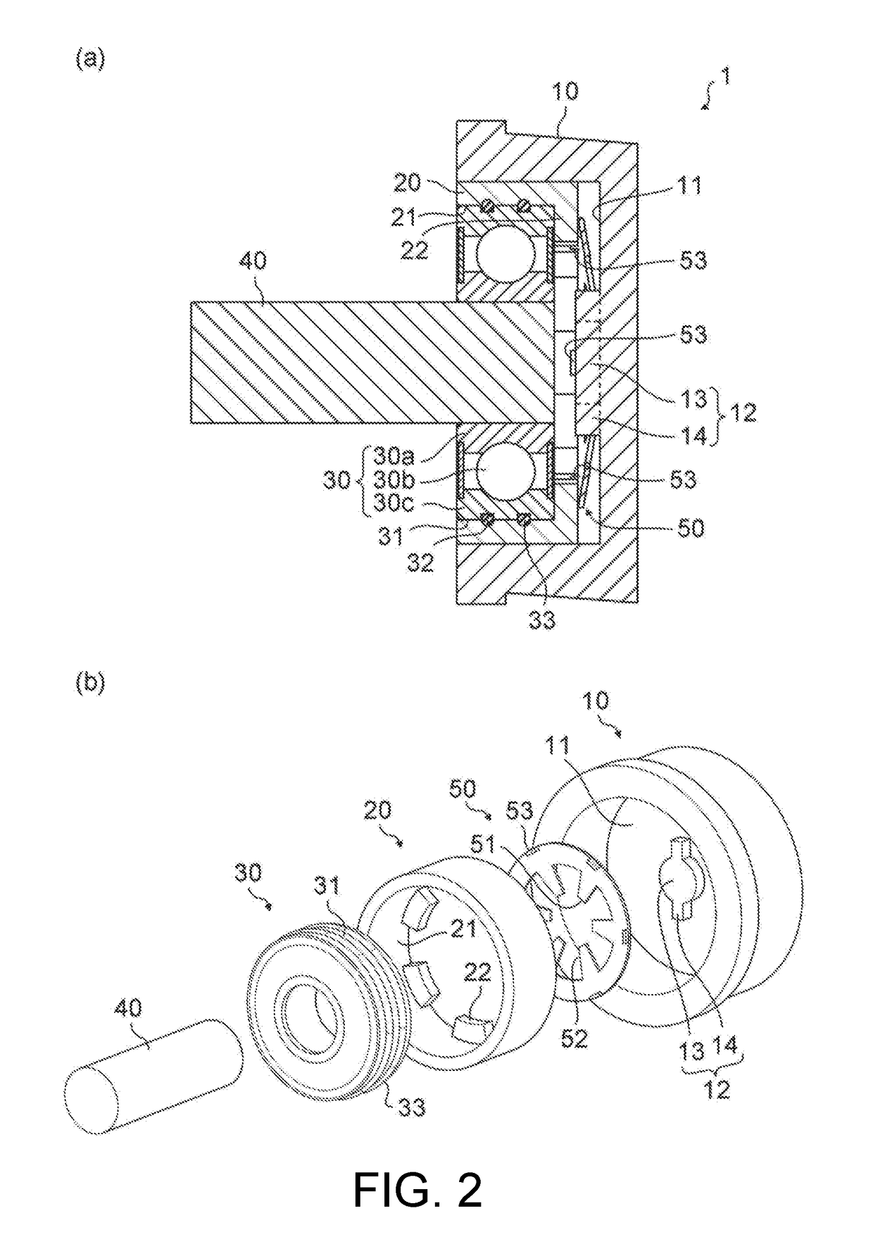
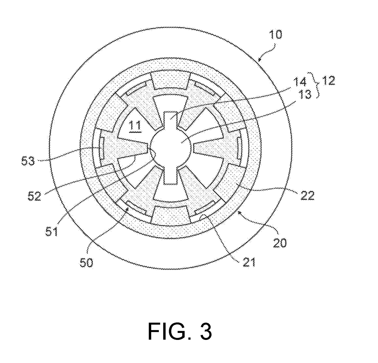
[0033]Explained below with reference to FIG. 2 is a configuration of a bearing assembly unit according to the first embodiment of the disclosure; in particular, a configuration of an outer holder, an inner holder, a first rolling bearing element (hereinafter, simply called a ‘rolling bearing element’) and a shaft. (a) of FIG. 2 is a schematic cross-sectional view, along an axial direction, of the bearing assembly unit according to the present embodiment, and meanwhile (b) of FIG. 2 is a schematic exploded perspective view of the bearing assembly unit according to the present embodiment.

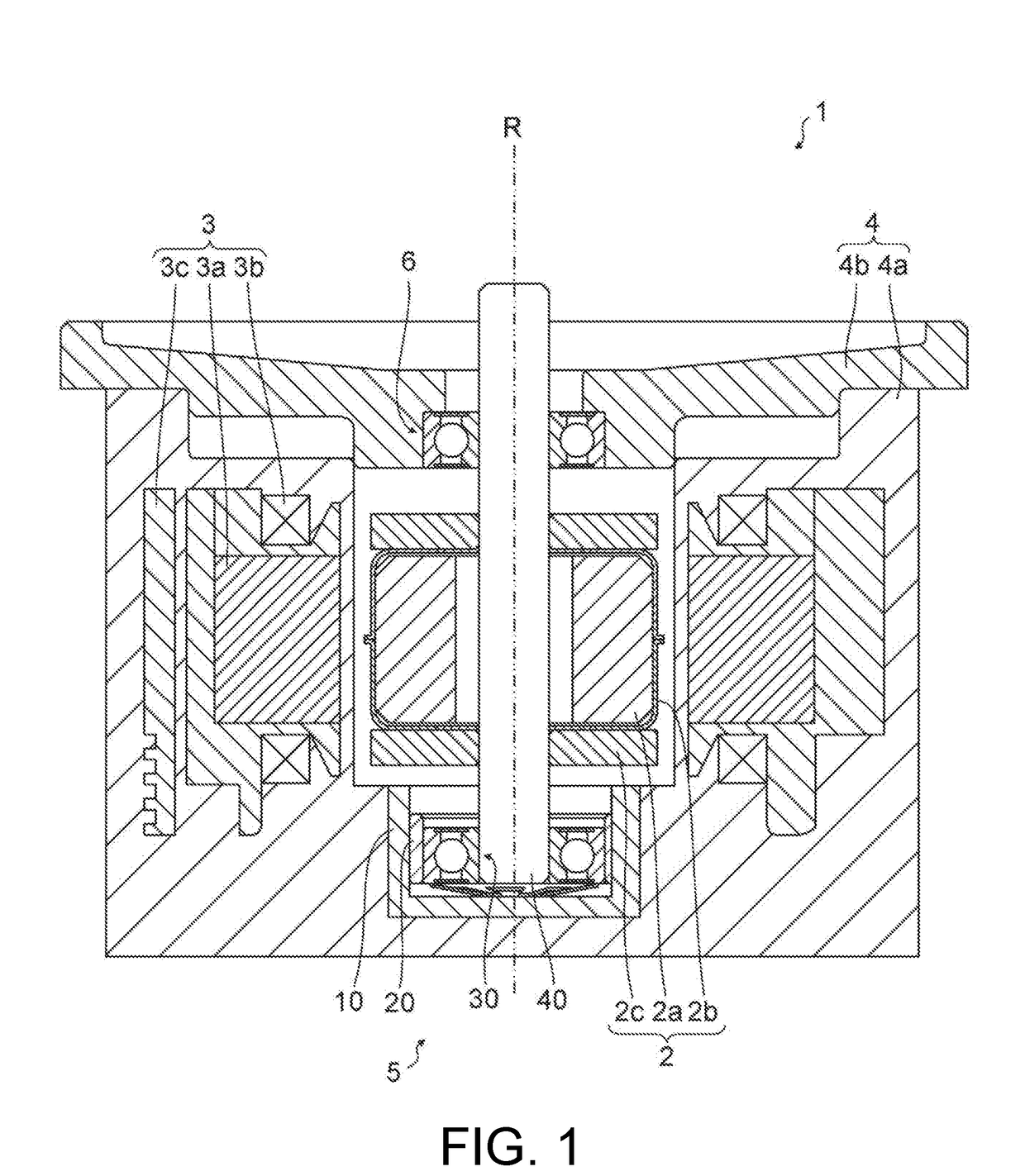
[0034]The bearing assembly unit 5 supports the rotor part 2 and the stator part 3, of the motor 1, in such a way as to enable a relative rotation between these two parts; and the bearing assembly unit 5 includes an outer holder 10, an inner holder 20, a rolling bearing element 30, a shaft 40, and a rotation restriction mechanism (having a first engagement part 12 and a second engagement part 22).

[0035...

second embodiment

[0050](a) of FIG. 4 is a schematic cross-sectional view, along an axial direction, of a bearing assembly unit relating to a second embodiment of the disclosure, and meanwhile (b) of FIG. 4 is a schematic exploded perspective view of the bearing assembly unit according to the present embodiment. FIG. 5 is a schematic plan view of a rotation restriction mechanism according to the present embodiment, the rotation restriction mechanism being viewed in an axial direction. In the explanation below; with regard to a configuration that is the same as a corresponding configuration in the first embodiment, the same reference numeral is provided for the configuration in the view, and the explanation is omitted; and meanwhile, only a configuration that is different from the corresponding configuration in the first embodiment is explained.

[0051]The rotation restriction mechanism shown in the second embodiment is configured with a first engagement part 16 and a second engagement part 24. Concrete...


PUM


Abstract

A bearing assembly unit (5) includes an outer holder (10) configured with a cylindrical member; an inner holder (20) that is configured with a cylindrical member, and inserted into an inner circumferential surface of the outer holder (10) so as to be movable in an axial direction; and a rolling bearing element (30) which is inserted into an inner circumferential section of the inner holder (20) so as to be fixed at least in a circumferential direction, and into which a shaft (40) is inserted so as to be fixed there; wherein, between the outer holder (10) and the inner holder (20), there is provided a rotation restriction mechanism (12, 22) that prevents a relative rotation between the outer holder (10) and the inner holder (20).

Description

CROSS REFERENCE TO RELATED APPLICATION[0001]The disclosure claims priority under 35 U.S.C. § 119 to Japanese Application No. 2017-148040 filed Jul. 31, 2017, the entire content of which is incorporated herein by reference.FIELD OF THE DISCLOSURE[0002]The disclosure relates to a bearing assembly unit and a motor.BACKGROUND[0003]Conventionally, known is a motor in which a bearing assembly unit, including a rolling bearing element, is placed between a rotor part and a stator part. In the motor, used is the bearing assembly unit in which a sleeve is so provided as to surround a bearing element in order to prevent an inner ring and an outer ring of the bearing element from rolling together, and the sleeve and the bearing element are fixed to each other by use of an adhesive (for example, refer to Patent Document 1).PRIOR ART DOCUMENTPatent Document[0004]Patent Document 1: Japanese Unexamined Patent Application Publication No. 2013-44435SUMMARY OF DISCLOSUREProblem to Be Solved[0005]Unfor...

Claims


Application Information

Patent Timeline
Patent Type & Authority Applications(United States)
IPC IPC(8): F16C19/16F16C33/58
CPCF16C19/16F16C33/58F16C33/38F16C33/583H02K5/173F16C25/083F16C35/077F16C2300/54F16C2226/76F16C2229/00H02K5/1732
Inventor ISAJI, NAOYAKUROSAWA, HIRONORI
Owner SANKYO SEIKI MFG CO LTD
Why Eureka
Try Eureka