Mass flow regulation in roller devices

a technology of mass flow regulation and roller devices, which is applied in the direction of measuring devices, roll speed control devices, manufacturing tools, etc., can solve the problems of difficult measurement of speed at the outlet of the roller stand, and the difficulty of measuring speed at the outlet of the first roller stand, and achieve the effect of high control precision

Active Publication Date: 2019-02-07
SMS GRP GMBH
View PDF7 Cites 1 Cited by
  • Summary
  • Abstract
  • Description
  • Claims
  • Application Information

AI Technical Summary

Benefits of technology

The technical effect of this patent is that it provides a way to manage a roller line (specifically, a cold one) with very precise controls even during times when its structure needs to be simplified.

Problems solved by technology

The technical problem addressed in this patent relates to accurately monitoring the thickness of the roller band during transport through the roller gap in roller device settings. This may be challenging because measurements of speed at the output of the roller stand may be difficult due to factors such as slippage, emulsion/oil, vapor, or limited space availability. Current methods rely on indirect measures like determining the de facto dimension of the roller line or calculating the speed based on sensor data and electronic equipment.

Method used


Image

  • Mass flow regulation in roller devices
  • Mass flow regulation in roller devices

Examples


Embodiment Construction

[0021]In what follows, preferred embodiments are described, employing the figures. With this, similar or identically acting elements are provided with identical reference symbols, and in part a repeated description of these elements is dispensed with, to avoid redundancies.

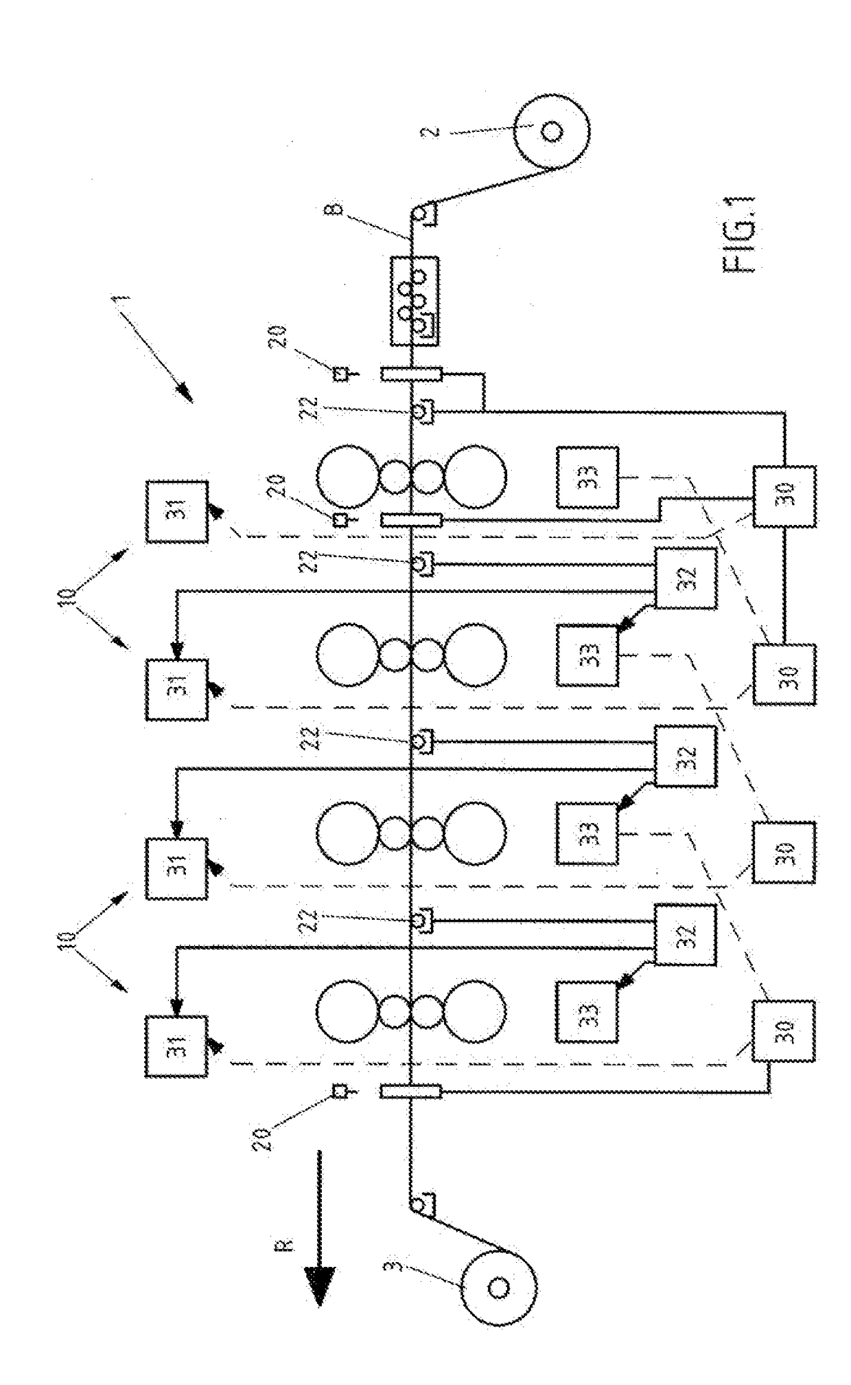
[0022]FIG. 1 is a schematic depiction of a tandem line or roller line 1 with four roller stands 10 situated one behind the other, preferably for a cold roller line. Roller line 1 in the current example has an unwinding winch 2 and a takeup winch 3. A roller band or roller stock B is fed to roller stands 10 in transport direction R, if necessary via return pulleys, and after passing roller stands 10, i.e. after completion of the roller processing, is wound up by takeup winch 3. The feeding and removal of roller band B via winches 2 and 3, is only an example; roller band B can also be brought to roller stands 10 by another means and be removed for further processing, for transport, etc.

[0023]To distinguish the rolle...


PUM

PropertyMeasurementUnit
Thicknessaaaaaaaaaa
Speedaaaaaaaaaa
Tensionaaaaaaaaaa

Abstract

A method for controlling a roller line, preferably a cold roller line, which has one or more roller stands each with two working rollers, which form a roller gap, through which a roller band is transportable. One or both working rollers can shift relative to the other, so that the roller gap is adjustable. The method includes making available a reference speed, which is a parameter for controlling the roller line, measurement of speed of the roller band before the inlet into the roller gap, measurement of the thickness of the roller band before the inlet into the roller gap, and adjustment of the roller gap of one or more roller frames in the roller line on the basis of measured speed and thickness before the inlet into the roller gap as well as the reference speed.

Description


Claims


Application Information

Patent Timeline
Owner SMS GRP GMBH
Why Eureka
Try Eureka