Image heating apparatus and image forming apparatus
a technology of heating apparatus and heating apparatus, which is applied in the direction of electrographic process apparatus, instruments, optics, etc., can solve the problems of delayed first print out time (fpot), image failure, and inability to generate desired longitudinal temperature distribution by predetermined timing, etc., and achieve good output image and reduce fpot
- Summary
- Abstract
- Description
- Claims
- Application Information
AI Technical Summary
Benefits of technology
Problems solved by technology
Method used
Image
Examples
example 1
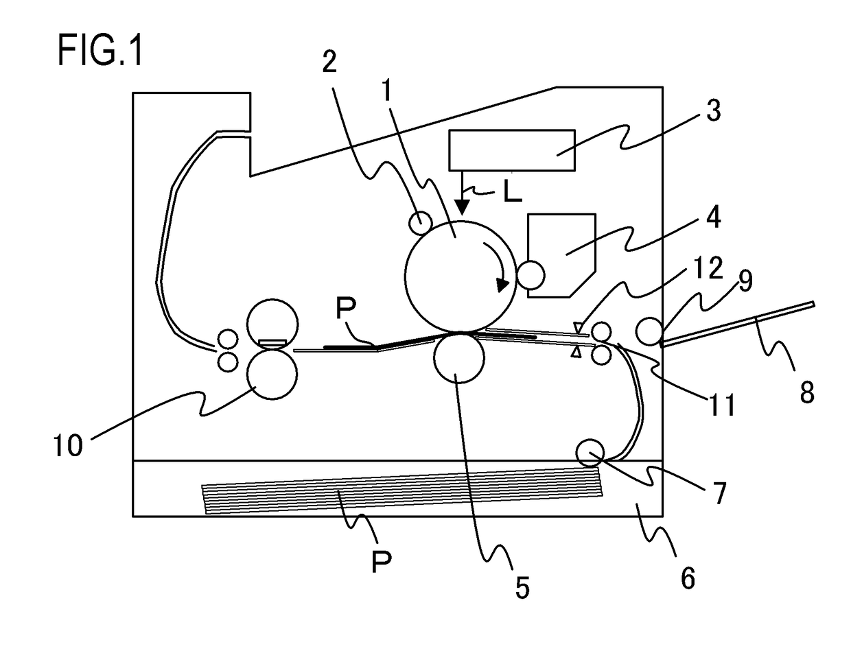
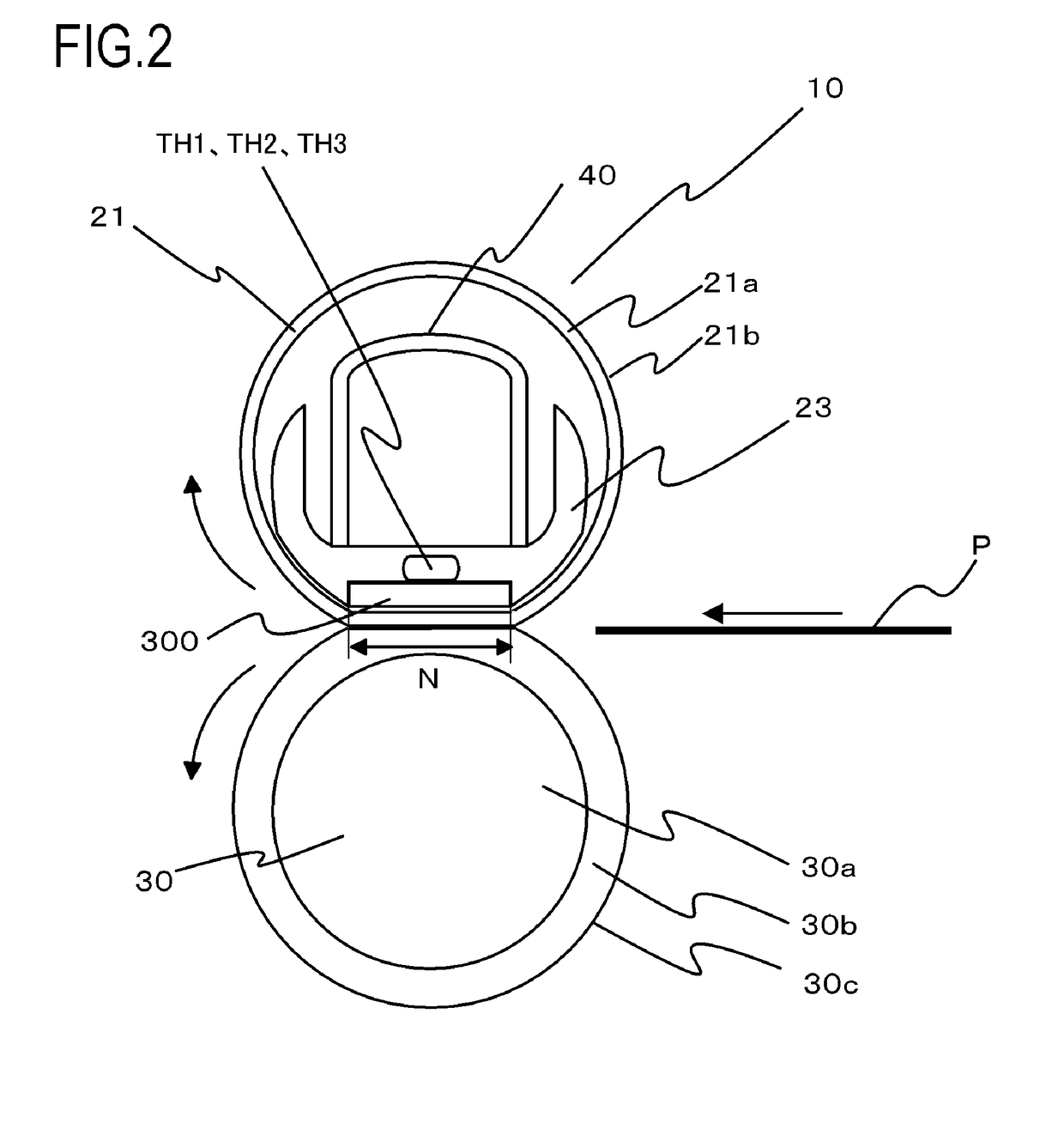
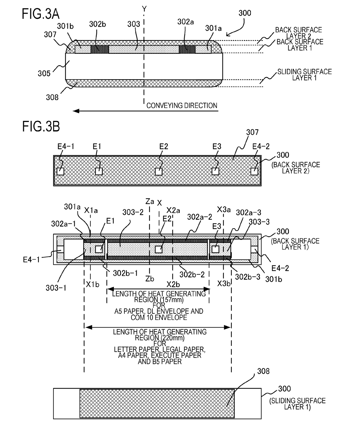
[0032]FIG. 1 is a schematic cross-sectional view depicting a general configuration of a laser beam printer (hereafter “laser printer”), which is an image forming apparatus according to an example of the present invention. A photosensitive drum 1 is rotationally driven in the arrow direction, and the surface of the photosensitive drum 1 is uniformly charged by a charging roller 2, which is a charging apparatus. A laser scanner 3 scans and exposes the surface of the photosensitive drum 1 using a laser beam L, of which ON / OFF is controlled in accordance with the image information, so as to form an electrostatic latent image (latent image forming process). A developing apparatus 4 allows toner to adhere to this electrostatic latent image, and develops the toner image onto the photosensitive drum 1 (developing process). In a transfer nip portion where a transfer roller 5 and the photosensitive drum 1 are pressure-contacted, the toner image formed on the photosensitive drum 1 is transferr...
modification 1
[0088]As Modification 1 of Example 1, the present invention may be applied to a configuration depicted in FIGS. 12A and 12B. In other words, a heater 1300 of Modification 1 is constituted by heat generating resistors, which are intermittently formed and connected parallel with the conductor. By decreasing the area of the heat generating resistors like this, a heating amount equivalent to Example 1 can be implemented using a heat generating resistor paste material of which sheet resistance is lower. Normally the PTC characteristic of the heat generating resistor paste material is higher as the sheet resistance is lower, and in the case of detecting temperature using the resistance temperature characteristic of the heat generating resistor, as in Example 1, the detection accuracy can be higher as the absolute value of the TCR value is higher. Further, if each heat generating resistor 1302a-1, 1302a-2, 1302a-3, 1302b-1, 1302b-2 and 1302b-3 connected in parallel is formed diagonally wit...
modification 2
[0089]As Modification 2 of Example 1, the present invention may be applied to a configuration depicted in FIGS. 13A and 13B. In other words, a heater 2300 of Modification 2 is constituted by disposing a heat generating resistor 2302, conductors 2301 and 2303, and electrodes E21 to E24 on the sliding surface side (sliding surface layer 1) of the film 21. The conductor 2303, which is the second conductor, and conductors 2303-1, 2303-2 and 2303-3 connected to each heat generating resistor, are interconnected in the conductor 2303-4. By using the configuration of Modification 2, heat generated in each heat generating resistor 2302-1, 2302-2 and 2302-3 can be transferred to the film 21 at a higher speed. This means that the image heating apparatus can be heated more quickly, and first print out time (FPOT) can be decreased. On the other hand, the heater substrate may become larger since the conductors 2301-1, 2301-2, 2301-3, 2303-12303-2, 2303-3 and 2303-4, and the electrodes E21, E22, E...
PUM
 Abstract
Description
Claims
Application Information
 - R&D
- Intellectual Property
- Life Sciences
- Materials
- Tech Scout
- Unparalleled Data Quality
- Higher Quality Content
- 60% Fewer Hallucinations
Browse by: Latest US Patents, China's latest patents, Technical Efficacy Thesaurus, Application Domain, Technology Topic, Popular Technical Reports.
© 2025 PatSnap. All rights reserved.Legal|Privacy policy|Modern Slavery Act Transparency Statement|Sitemap|About US| Contact US: help@patsnap.com


