Multi-Vital Sign Detector in an Electronic Medical Records System

a multi-vital sign and electronic medical record system technology, applied in the field of detecting multiple vital signs, can solve the problems of cumbersome affixing of sensors to patients and implementation of problematic sensors

Inactive Publication Date: 2019-02-14
VVV HLDG LTD +1
View PDF6 Cites 81 Cited by
  • Summary
  • Abstract
  • Description
  • Claims
  • Application Information

AI Technical Summary

Problems solved by technology

Prior techniques of capturing multiple vital signs from human subjects have implemented problematic sensors and have been very cum

Method used


Image

  • Multi-Vital Sign Detector in an Electronic Medical Records System
  • Multi-Vital Sign Detector in an Electronic Medical Records System
  • Multi-Vital Sign Detector in an Electronic Medical Records System

Examples


Embodiment Construction

[0068]In the following detailed description, reference is made to the accompanying drawings that form a part hereof, and in which is shown by way of illustration specific implementations which may be practiced. These implementations are described in sufficient detail to enable those skilled in the art to practice the implementations, and it is to be understood that other implementations may be utilized and that logical, mechanical, electrical and other changes may be made without departing from the scope of the implementations. The following detailed description is, therefore, not to be taken in a limiting sense.

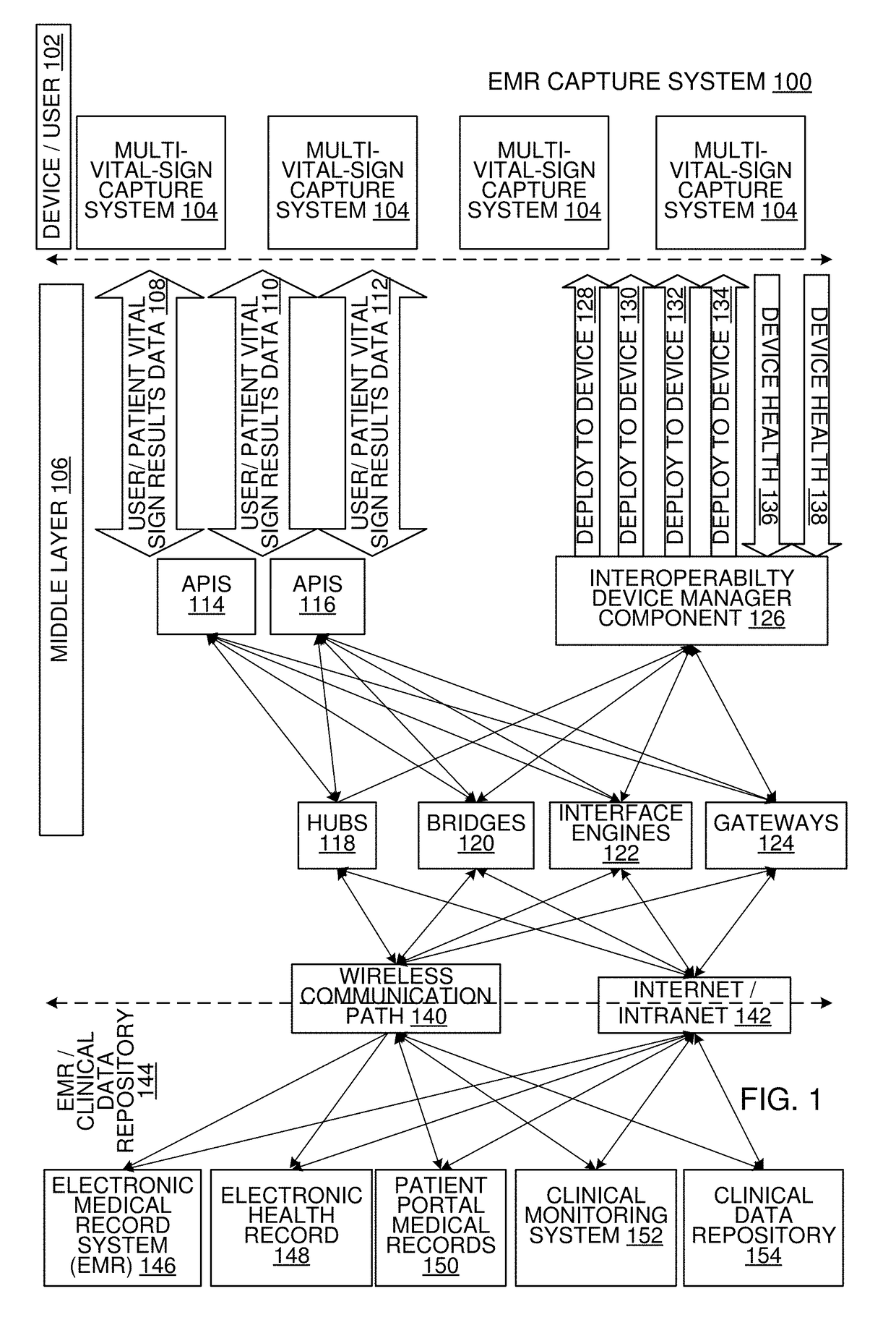
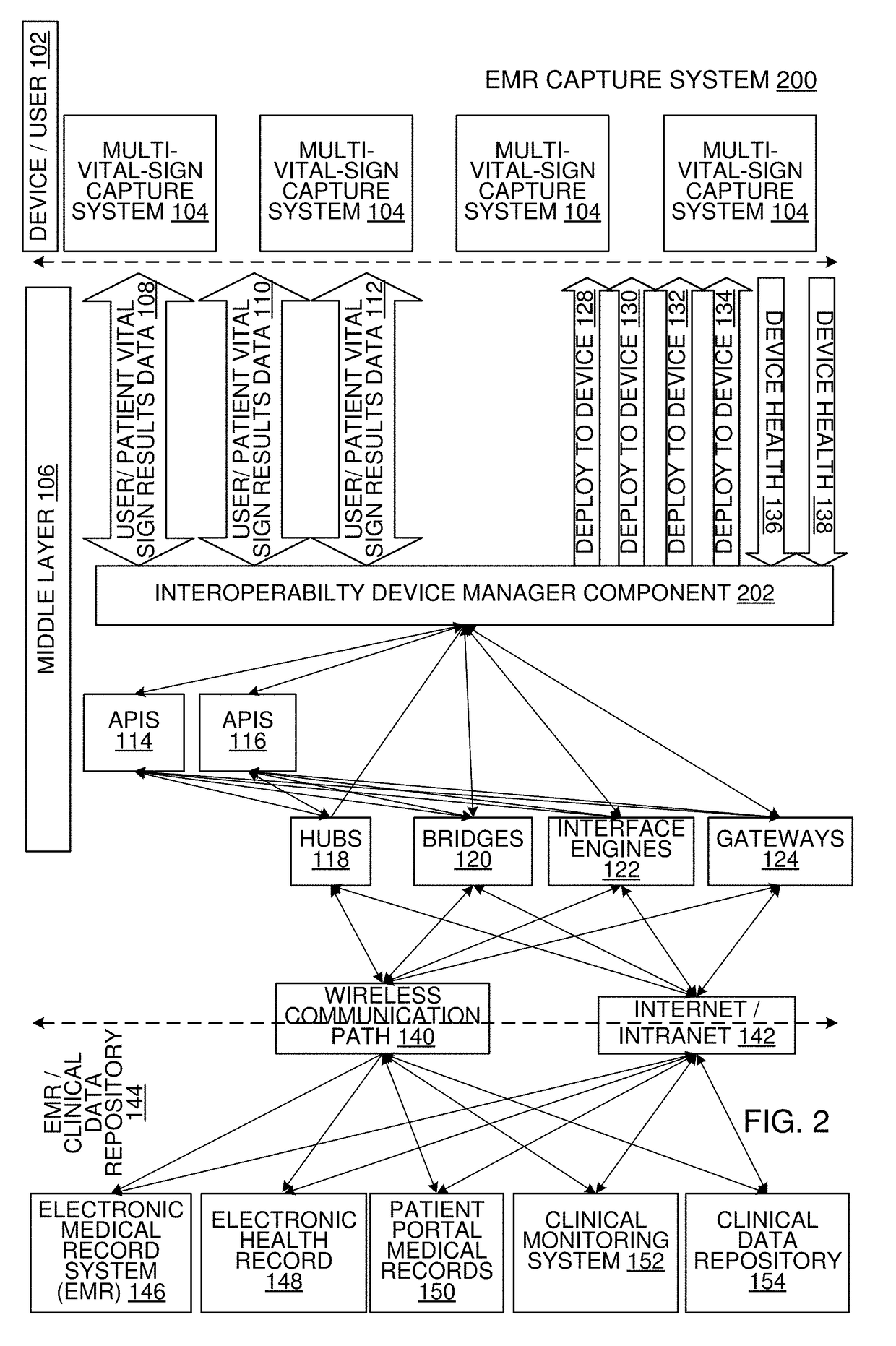
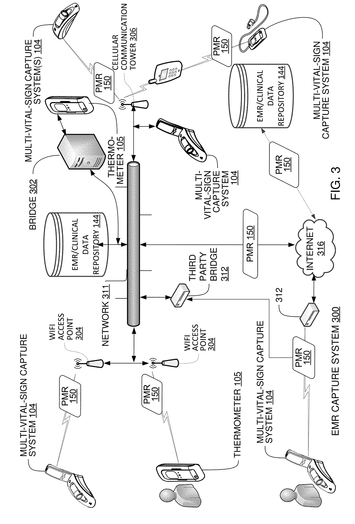
[0069]The detailed description is divided into eleven sections. In the first section, an overview is shown. In the second section, apparatus of an electronic medical records capture system are described. In the third section, implementations of apparatus of multi-vital-sign capture systems are described. In the fourth section, implementations of non-touch table-based tempera...


PUM


Abstract

In one implementation, a device detects multiple vital signs from sensors such as a digital infrared sensor, a photoplethysmogram (PPG) sensor and at least one micro dynamic light scattering (mDLS) sensor, and thereafter in some implementations the vital signs are transmitted to, and stored by, an electronic medical record system.

Description

FIELD[0001]This disclosure relates generally to detecting multiple vital signs and communicating detected multiple vital signs to a medical records system.BACKGROUND[0002]Prior techniques of capturing multiple vital signs from human subjects have implemented problematic sensors and have been very cumbersome in terms of affixing the sensors to the patient, recording, storing and forwarding the vital signs to appropriate parties.BRIEF DESCRIPTION[0003]In one aspect, a device measures temperature, heart rate at rest, heart rate variability, respiration, SPO2, blood flow, blood pressure, total hemoglobin (SpHb), PVi, methemoglobin (SpMet), acoustic respiration rate (RRa), carboxyhemoglobin (SpCO), oxygen reserve index (ORi), oxygen content (SpOC), ECG and / or EEG of a human.[0004]In another aspect, a device to estimate a body core temperature includes a microprocessor, a digital infrared sensor that is operably coupled to the microprocessor with no analog-to-digital converter being opera...

Claims


Application Information

Patent Timeline
IPC IPC(8): A61B5/024G06F19/00A61B5/00A61B5/0255
CPCG16H40/63A61B5/02416A61B5/0024A61B5/0255A61B5/0205A61B5/02255A61B5/0008A61B5/0006A61B5/0261A61B5/0833A61B5/02405A61B5/0816A61B2560/045G16H10/60G16H40/67G16H40/40
Inventor KHACHATURIAN, MARKBARRET, JOHNSMITH, MICHAELCRAWLEY, MARTINGROSS, IRWINCRONIN, MICHAELTURNBULL, DEREKCHERAPY, CHRISTINECOTTREAU, PETERWILLIAMS, PATRICKTORRES, ALEXANDEREPHRATH, JONATHAN
Owner VVV HLDG LTD
Why Eureka
Try Eureka