Method for manufacturing bearing cage

a manufacturing method and cage technology, applied in the direction of mechanical equipment, rotary machine parts, other domestic objects, etc., can solve the problems of affecting the durability of the cage, damage at this portion, and the resin cage of the bearing manufactured by injection molding often breaks, so as to suppress the degradation of the strength of the cage and improve the strength of the weld line

Active Publication Date: 2019-02-21
NSK LTD
View PDF0 Cites 2 Cited by
  • Summary
  • Abstract
  • Description
  • Claims
  • Application Information

AI Technical Summary

Benefits of technology

[0030]According to the method for manufacturing the bearing cage of the present invention, a pressure gradient occurs in the cavity, and the melted resin flows from the resin injection gate whose cross-sectional area is large and pressure is high toward the resin reservoir whose pressure is low. Orientation of the reinforcing fiber materials oriented perpendicular (radial direction) to the flow direction (circumferential direction) upon the merger of melted resin is controlled by the flow of the melted resin and faces the circumferential direction. Therefore, the strength of the weld line is improved. As a result, it is possible to suppress strength degradation of the cage.

Problems solved by technology

In this ways, the resin cage for a bearing manufactured by injection molding often breaks due to a weld line whose strength is weak.
In particular, when the weld line is formed at a portion where stress is most liable to concentrate (for example, a bottom portion whose axial thickness is thinnest in a pocket or a curved portion at a corner where an annular portion intersects with a pillar), damage is liable to occur at this portion, and durability of the cage is impaired.

Method used


Image

  • Method for manufacturing bearing cage
  • Method for manufacturing bearing cage
  • Method for manufacturing bearing cage

Examples


first embodiment

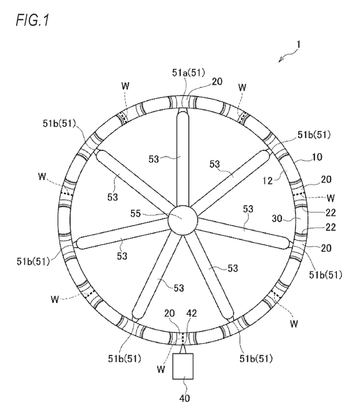
[0043]FIG. 1 shows a bearing cage 1 of this embodiment (hereinafter sometimes simply referred to as a cage). The cage 1 is a so-called crown-shaped cage, and includes a substantially annular base portion 10, a plurality and an even number (fourteen in this embodiment) of pillars 20 protruding in an axial direction at predetermined intervals in a circumferential direction from an axial lateral surface 12 of the base portion 10, and a plurality and an even number (fourteen in this embodiment) of pockets 30 holding rolling elements (not shown) of a bearing formed by mutually facing surfaces 22, 22 of a pair of adjacent pillars 20, 20 and the axial lateral surface 12 of the base portion 10. That is, the numbers of the pillars 20 and the pockets 30 are the same and a plurality and an even number of the pillars 20 and the pockets 30 are formed, and the pillars 20 are provided on both circumferential sides of respective pockets 30.

[0044]In a manufacturing method of such a cage 1, multi-poi...

second embodiment

[0051]Next, a method for manufacturing a bearing cage of a second embodiment according to the present invention will be described with reference to the drawings.

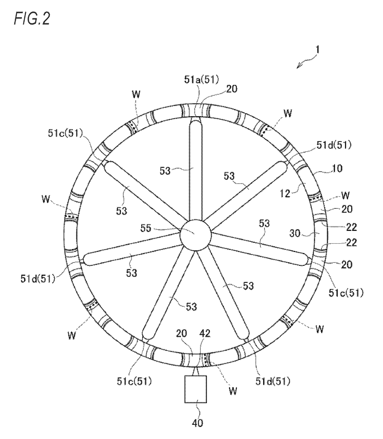
[0052]As shown in FIG. 2, this embodiment is the same as the first embodiment in that among a plurality of (seven) gates 51, a cross-sectional area of one gate 51 (hereinafter sometimes referred to as a large-diameter gate 51a) is larger than cross-sectional areas of the other gates 51. On the other hand, this embodiment is different from the first embodiment in that for the other gates 51, a gate having a large cross-sectional area (hereinafter sometimes referred to as a medium-diameter gate 51c) and a gate having a small cross-sectional area (hereinafter sometimes referred to as a small-diameter gate 51d) are arranged alternately in a circumferential direction.

[0053]In such a configuration, the melted resin injected into a cavity from the gates 51 and flowing to both sides in the circumferential direction of the gates 51 m...

third embodiment

[0057]Next, a method for manufacturing a bearing cage of a third embodiment according to the present invention will be described with reference to the drawings.

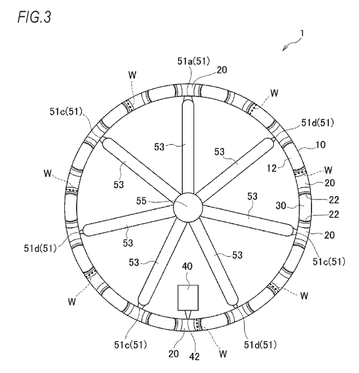
[0058]As shown in FIG. 3, this embodiment is different from the second embodiment in that a resin reservoir 40 is provided on an inner circumferential surface of a pillar20. Other configurations are the same as those of the second embodiment, and the same effects as those of the second embodiment can be exerted.


PUM

PropertyMeasurementUnit
cross-sectional areaaaaaaaaaaa
strengthaaaaaaaaaa
thicknessaaaaaaaaaa

Abstract

A resin reservoir capable of storing the melted resin is provided in the pillar radially facing the pillar provided with the resin injection gate having a cross-sectional area larger than those of the other resin injection gates among a plurality of the pillars not provided with the resin injection gate or the pillar in the vicinity of the pillar facing the pillar provided with the resin injection gate having a cross-sectional area larger than those of the other resin injection gates among the plurality of the pillars not provided with the resin injection gate. A cross-sectional area of a communicating portion of the resin reservoir which communicates with the pillar is smaller than the smallest of cross-sectional areas of a plurality of the resin injection gates.

Description

TECHNICAL FIELD[0001]The present invention relates to a method for manufacturing a bearing cage.BACKGROUND ART[0002]In general, a bearing cage is manufactured by injection molding. Specifically, as shown in FIG. 11, a bearing cage is manufactured by forming a circular cavity 140 corresponding to a bearing cage which is a molded body in a mold, injecting a melted resin material (thermoplastic resin) from a resin injection gate 150 provided on a peripheral portion of the cavity 140, and cooling and solidifying.[0003]The melted resin injected to the cavity 140 forms two flows and flows to two sides in a circumferential direction in the cavity 140, then merges at a position on an opposite side facing the resin injection gate 150 in a radial direction, and is joined to each other, thus a weld line 100W is formed. In general, it is well-known that since such an injection molded resin cage for a bearing is a cage in which the melted resin is fused and integrated, uniform mixing of the melt...

Claims


Application Information

Patent Timeline
Patent Type & Authority Applications(United States)
IPC IPC(8): B29C45/27F16C33/44
CPCB29C45/2708F16C33/44B29K2101/12B29L2031/04B29K2309/08F16C2208/04B29C45/0025B29C45/0046B29C45/2616B29C45/2628B29C45/2669B29C2045/0006B29C2045/0027B29C2045/0044F16C19/06F16C33/416F16C33/498F16C2300/02
Inventor KURAMOTO, YOSHIKAZUAIHARA, NARIAKIHIRAMOTO, TAKAYUKI
Owner NSK LTD
Why Eureka
Try Eureka