Hidden fastener unit and related method of use

a fastener and hidden technology, applied in the field of fastener units, can solve the problems of affecting the safety of users, and unable to engage the groove, and achieve the effect of convenient removal and discarded

Active Publication Date: 2019-02-21
NAT NAIL
View PDF0 Cites 12 Cited by
  • Summary
  • Abstract
  • Description
  • Claims
  • Application Information

AI Technical Summary

Benefits of technology

[0020]The current embodiments of the fastener unit and related methods of use provide benefits in hidden fasteners that previously have been unachievable. For example, where the fastener unit includes a multi-dimensioned fastener hole defined by the spacer body, the spacer body can be configured to hold a fastener therein, yet not split or become damaged when the fastener is advanced through the spacer body. Where the fastener includes one or more fracturable joints between the spacer body and one or more of the resilient compression elements, those elements can be easily removed and discarded from the unit to fit a particular joist combination or confined space. Where the unit includes the resilient compression element, that element can secure and hold the fastener unit in place adjacent the groove, without the need for additional hands to hold the unit. This can enable a user to place multiple fastener units along a board groove, install another board adjacent those units, and then come back and secure all the fastener units so that the boards are held in a fixed manner relative to the underlying support structure. Where the grip element is included having one or more downward protrusions or cleats, those elements can forcibly engage the groove to prevent the board from creeping or moving during expansion and contraction thereof during and under different temperatures. Where the spacer body is of diminished thickness, the entire fastener unit can be well concealed between adjacent boards, yet provide firm securement of those boards to underlying support structure, and provide a gap large enough to accommodate a fastener head passing between the boards.

Problems solved by technology

The nails or screws can frequently become discolored over time, or can work themselves loose from the board and project upward from the board surface.
Not only are these results aesthetically displeasing, they can present safety hazards.
While the horizontal flanges can engage the grooves, these elements typically do not engage those grooves forcibly enough to tack the boards to the underlying joist and prevent them from moving during expansion and contraction under changing temperatures.
These systems typically also require a user to manually hold the plate in alignment with one or more grooves of the boards as the fastener is advanced, which can be cumbersome.
Depending on the height of the base and the distance of the groove from the board lower surface, sometimes these items can be mismatched so that the flanges do not fit well in or align with the grooves.
In addition, the flanges are of a fixed thickness so that if that thickness is mismatched relative to a groove, the plate cannot fit in the groove, let alone secure the board to the underlying joist.
Further, where a support structure includes a double or triple joist, with two or more joists positioned immediately adjacent one another, the foregoing fastener systems might not be properly sized to conceal those joists or fit within the associated confined spaces.

Method used


Image

  • Hidden fastener unit and related method of use
  • Hidden fastener unit and related method of use
  • Hidden fastener unit and related method of use

Examples


embodiment 1

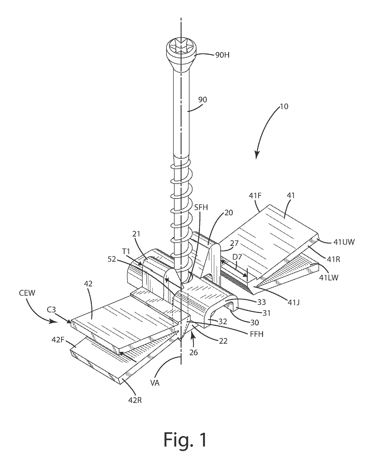
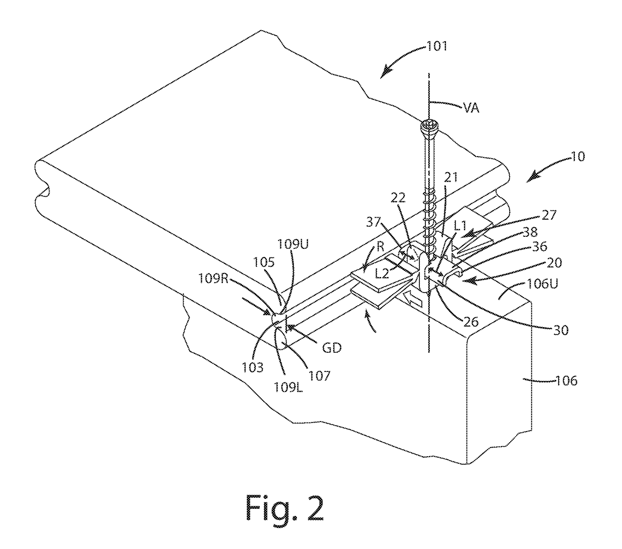
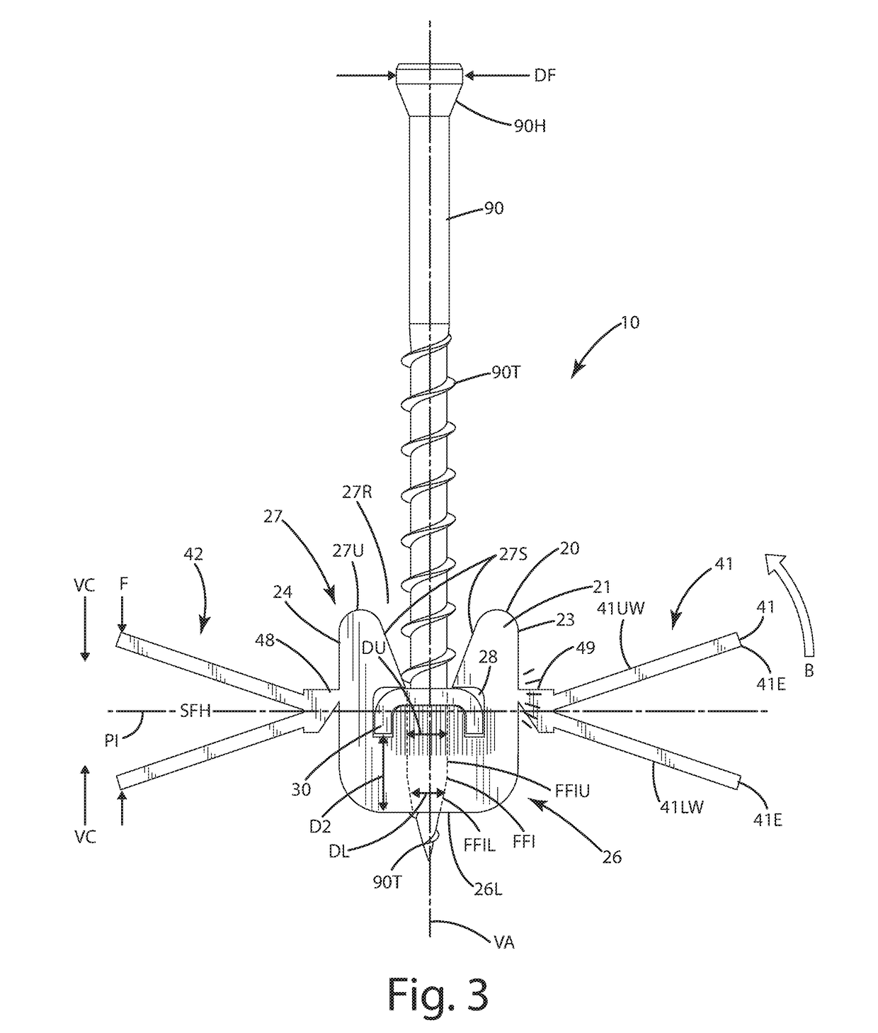
[0112 relates to a fastener unit adapted to secure at least one board to a support, the fastener unit comprising: a spacer body defining a first fastener hole having an upper portion having a first diameter and a lower portion, a threaded fastener disposed within the spacer body in the first fastener hole, the threaded fastener extending within the upper portion and the lower portion; a first joist leg and a second joist leg extending downward from the spacer body and configured to straddle and clamp a joist; and a grip element joined with the spacer body, the grip element defining a second fastener hole aligned with the first fastener hole, the grip element including a lower surface configured to engage a groove of a board.

embodiment 2

[0113 relates to Embodiment 1, wherein the grip element includes a pressure foot separated a distance from the spacer body by a distance, wherein the distance is configured to inset the pressure foot inward from a side surface of the board, beyond a slanted wall disposed under the groove, whereby a predetermined force can be distributed through the pressure foot to a bottom surface of the board without tipping the board.

embodiment 3

[0114 relates to Embodiment 1 or 2, wherein a first stabilizer bar extends from the first joist leg a predetermined distance, wherein a second stabilizer bar extends from the second joist leg the predetermined distance, wherein the first and second stabilizer bars are disposed at a common level, below the spacer body.

[0115]Embodiment 3 relates to any one of the preceding Embodiments, wherein each of the first and second joist legs each include outwardly extending portions that extend away from the spacer body, wherein the first and second stabilizer bars are joined with the respective outwardly extending portions.


PUM

PropertyMeasurementUnit
thicknessaaaaaaaaaa
thicknessaaaaaaaaaa
thicknessaaaaaaaaaa

Abstract

A fastener unit and related method for securing a board to a support is provided. The fastener unit includes a spacer block, a grip element extending from the spacer block and configured to fit in and engage a groove of the board, and one or more resilient compression elements extending from the spacer block. The one or more resilient compression elements can be a joist leg configured to engage a joist, or it can be vertically compressible toward a first plane that is transverse to a vertical axis of the spacer block so that portions of it can compress from an open mode to a compressed mode and fit within, then forcibly expand within the groove, thereby securing the spacer block in a position adjacent the groove to establish a gap between the board and another board. A related method of use also is provided.

Description

BACKGROUND OF THE INVENTION[0001]The present invention relates to a fastener unit configured to fasten workpieces, such as boards, to support structures, such as joists, and more particularly to a fastener unit that engages a groove in the side of a board to secure the board to a support structure.[0002]There are a variety of structures, such as decks, platforms and flooring, that include horizontal floors supported by an underlying support structure. The structures typically include boards that are placed side-by-side one another. The boards typically are arranged to extend cross support structures, such as joists, disposed under the boards at an angle, sometimes at a right angle. The boards usually are fastened to the joists using fasteners, such as nails or screws. The nails or screws can frequently become discolored over time, or can work themselves loose from the board and project upward from the board surface. Not only are these results aesthetically displeasing, they can pres...

Claims


Application Information

Patent Timeline
Patent Type & Authority Applications(United States)
IPC IPC(8): F16B12/20
CPCF16B12/2063E04F13/0894F16B2/14F16B12/26E04F2201/043E04F15/02044E04F15/10E04F2015/02094
Inventor VANDENBERG, ROGER A.HUTCHINGS, DOUGLAS F.
Owner NAT NAIL
Why Eureka
Try Eureka