Sound absorbing structure and pneumatic tire
a technology of sound absorption structure and pneumatic tire, which is applied in the direction of tyre parts, vehicle components, transportation and packaging, etc., can solve the problems of promoting sonic interference and difficult to reduce the resonance sound of certain frequencies of columns, and achieve the effect of reducing the resonance sound of certain frequencies
- Summary
- Abstract
- Description
- Claims
- Application Information
AI Technical Summary
Benefits of technology
Problems solved by technology
Method used
Image

Examples
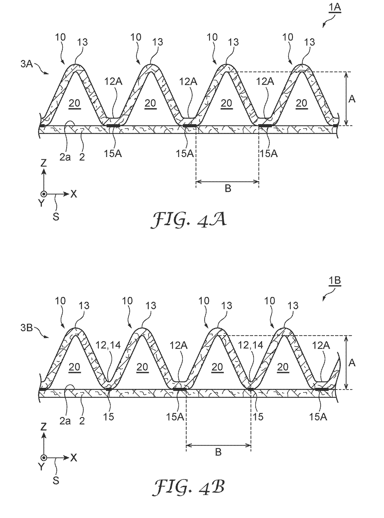
modified examples
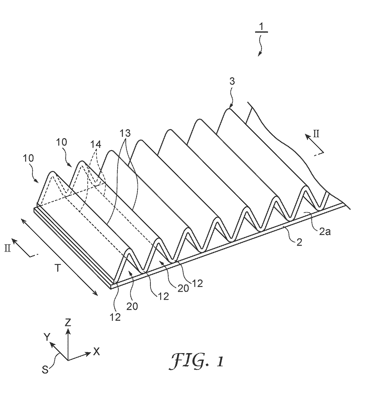
[0078]Embodiments of the present invention were described above, but the present invention is not limited to the abovementioned embodiments. For example, an example of a configuration was given in which the protrusions 10 extended along a direction orthogonal to the longitudinal direction of the base material 2, but extending along a direction orthogonal to the longitudinal direction is not necessary. Any configuration is possible provided that the protrusions 10 extend along a direction that crosses the longitudinal direction of the base material 2.
[0079]Additionally, another film-like nonwoven fabric (hereinafter referred to as “nonwoven fabric film” (not illustrated)) may be further laminated on the surface of the protrusions 10. The nonwoven fabric film is a thin film member that adjusts airflow resistance of the sound absorbing structure 1 and has functions for changing the sound absorption characteristics. Melt blown fiber, for example, may be used for the nonwoven fabric film...
example 1
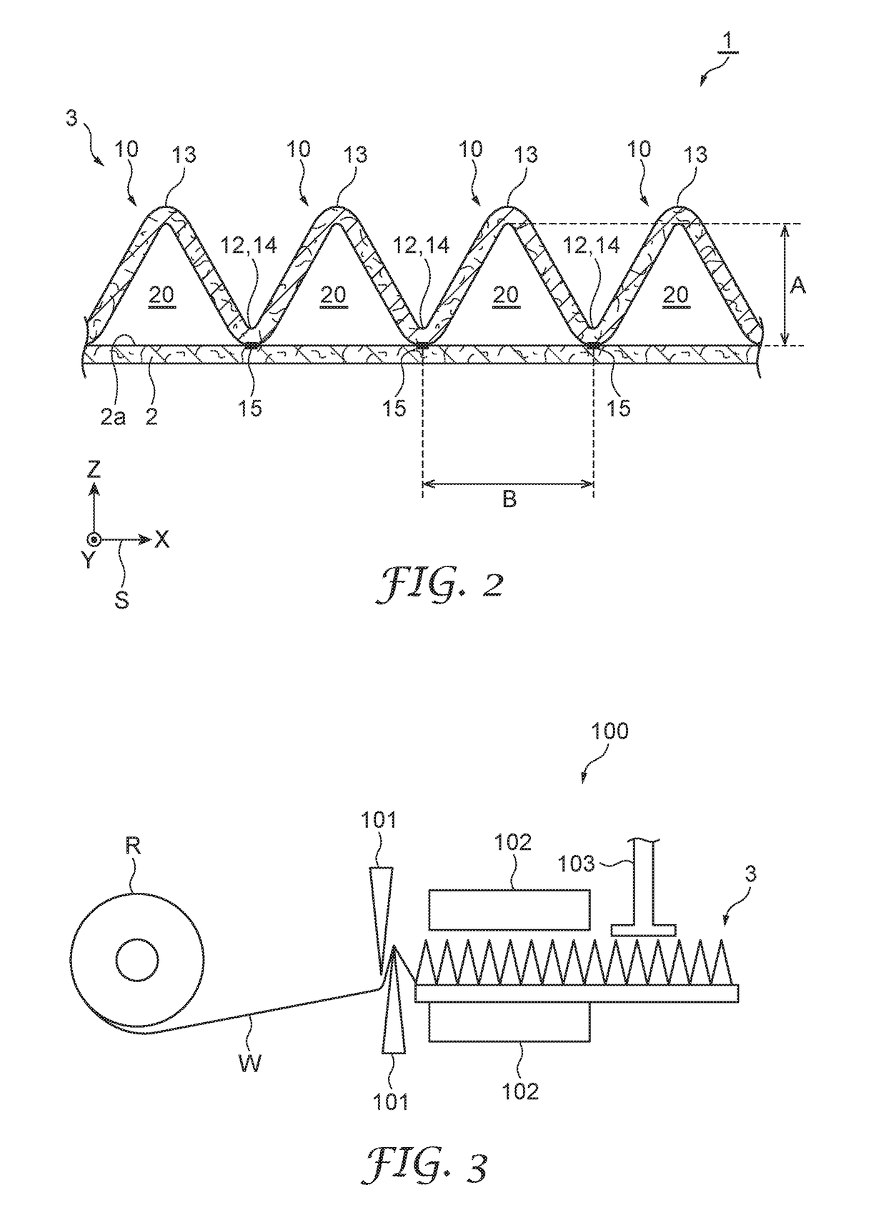
[0096]Protrusions were formed using a sheet member obtained by pleating a nonwoven fabric K-1 such that the projecting height of the protrusions was about 17.3 mm and the pitch of the protrusions was about 20 mm. This sheet member and the base material were bonded via the bonding layer of the base material. Thus, a sound absorbing structure of Example 1 was obtained. This sound absorbing structure was cut at a length in the longitudinal direction of the base material of 1700 mm and one layer thereof was disposed on the inner surface of the pneumatic tire (the back surface of the tread portion) such that the longitudinal direction of the base material followed the circumferential direction of the pneumatic tire. Double-sided tape was used to fix the sound absorbing structure to the inner surface of the pneumatic tire. A pneumatic tire for which a circumferential length of the inner space was about 1500 mm was prepared so that columnar resonance sound generated a maximum sound pressur...
example 2
[0097]Protrusions were formed using a sheet member obtained by pleating the nonwoven fabric K-1 such that the projecting height of the protrusions was about 25.9 mm and the pitch of the protrusions was about 30 mm. This sheet member and the base material were bonded via the bonding layer of the base material. Thus, a sound absorbing structure of Example 2 was obtained. This sound absorbing structure was disposed on the inner surface of the pneumatic tire in the same manner as Example 1.
PUM
 Abstract
Description
Claims
Application Information
 - R&D
- Intellectual Property
- Life Sciences
- Materials
- Tech Scout
- Unparalleled Data Quality
- Higher Quality Content
- 60% Fewer Hallucinations
Browse by: Latest US Patents, China's latest patents, Technical Efficacy Thesaurus, Application Domain, Technology Topic, Popular Technical Reports.
© 2025 PatSnap. All rights reserved.Legal|Privacy policy|Modern Slavery Act Transparency Statement|Sitemap|About US| Contact US: help@patsnap.com