Bicycle mounting mechanism and battery box assembly

a technology of mounting mechanism and battery box, which is applied in the direction of bicycle equipment, vehicle components, anti-theft cycle devices, etc., can solve the problems of unsatisfactory function, battery may run out of electricity, and need to recharge, so as to facilitate mounting and dismounting, facilitate quick installation, and provide a large faulty space

Active Publication Date: 2019-02-28
DONGGUAN HONG LIN IND CO LTD
View PDF0 Cites 13 Cited by
  • Summary
  • Abstract
  • Description
  • Claims
  • Application Information

AI Technical Summary

Benefits of technology

[0021](1) Through the structural design of the luggage carrier, the user can easily hold the battery box to pull the battery box out of the locating component unit along the sliding rails (or to install the battery box in the locating component unit), facilitating mounting and dismounting.
[0022](2) The installation of the b...

Problems solved by technology

However, the battery may run out of electricity and need to recharge, so the bicycle rider needs to remove the battery from...

Method used


Image

  • Bicycle mounting mechanism and battery box assembly
  • Bicycle mounting mechanism and battery box assembly
  • Bicycle mounting mechanism and battery box assembly

Examples


first embodiment

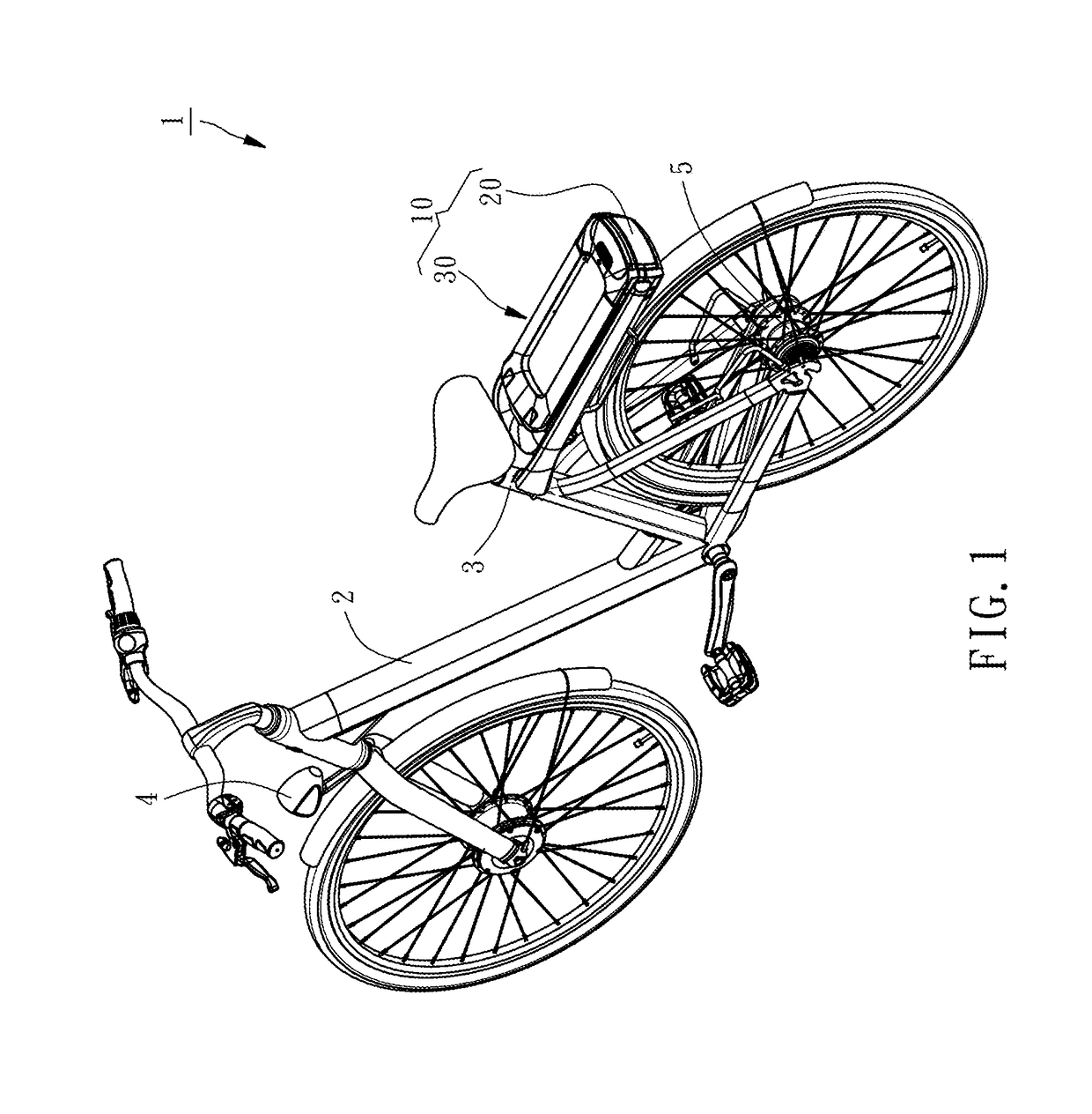
[0044]Referring to FIGS. 1-3, a bicycle mounting mechanism and battery box assembly 10 in accordance with the present invention is provided. It is mounted to a seat tube 3 of a bicycle frame 2 of a bicycle 1. The assembly 10 comprises a battery box 20 and a mounting mechanism 30.

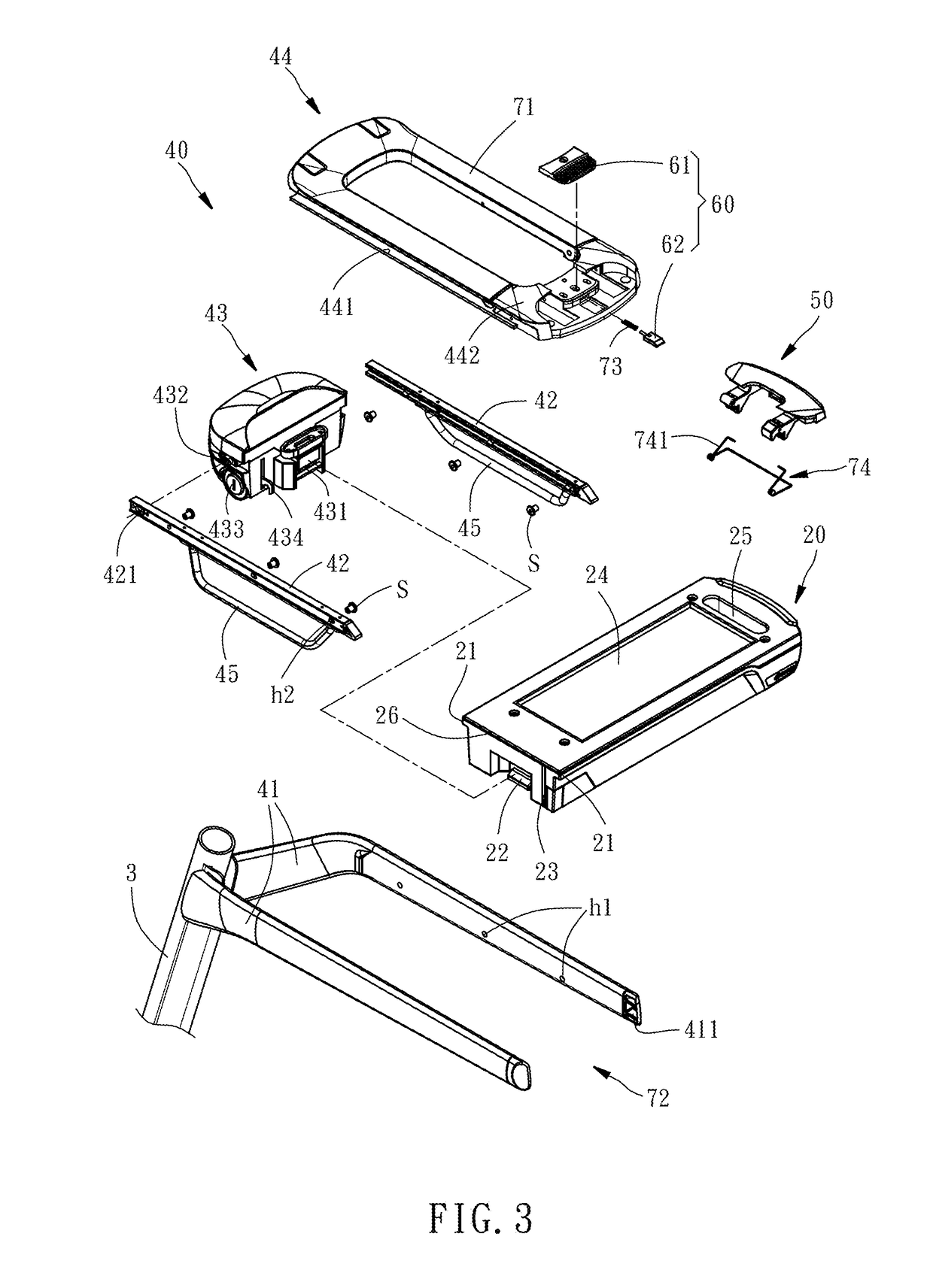
[0045]The battery box 20 is adapted for providing electricity, comprising two sliding blocks 21 respectively located at two opposite lateral sides thereof, a set of terminals 22 and a retaining portion 23 both disposed at a front side thereof, and an abutment recess 24 and an opening 25 located at a top side thereof. The abutment recess 24 has a predetermined depth. The opening 25 is disposed at a rear side relative to the abutment recess 24 and cuts through opposing top and bottom walls of the battery box 20 for allowing the user to grasp the battery box 20 conveniently.

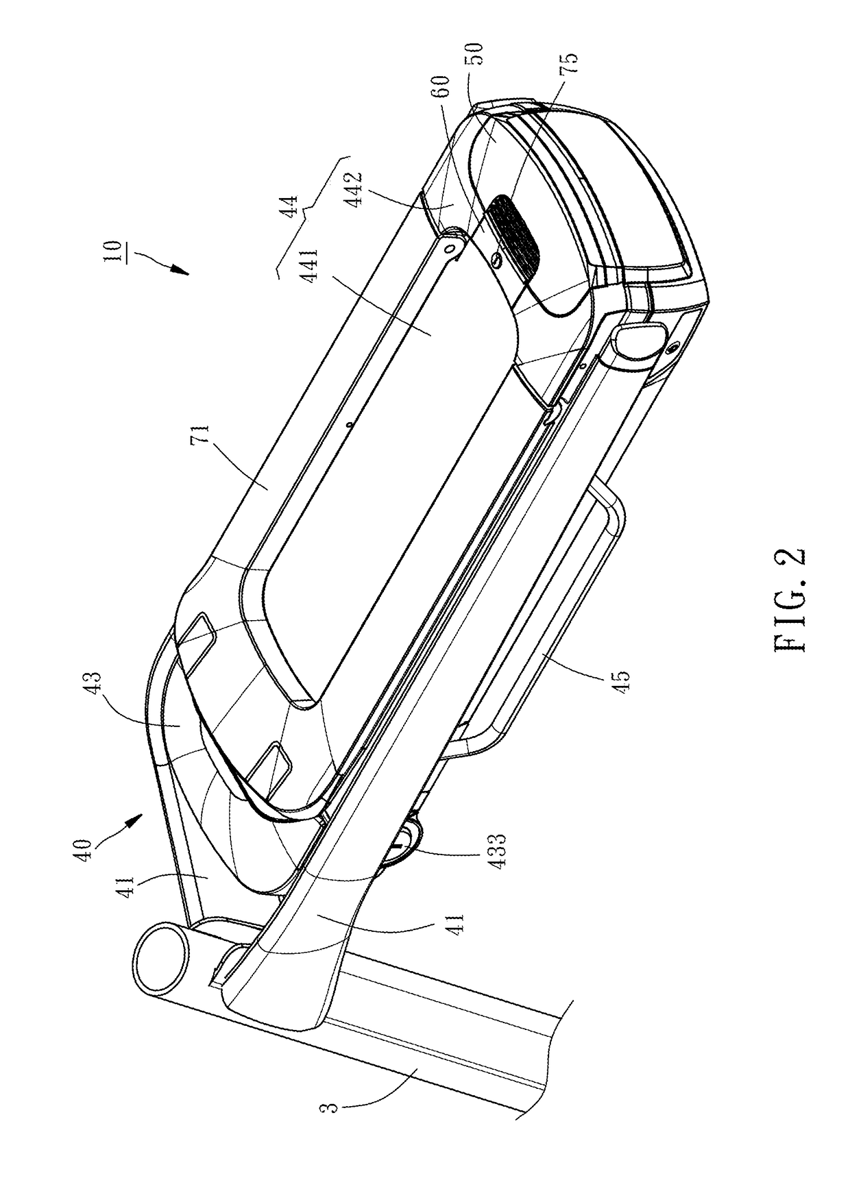
[0046]The mounting mechanism 30 comprises a locating component unit 40, a grip 50, a switch device 60 and a baffle 71.

[0047]The locating co...

fourth embodiment

[0060]Referring to FIG. 13, an assembly 10A of a luggage carrier 20A and a battery box 30A in accordance with the present invention is shown. The assembly 10A comprises a luggage carrier 20A and a battery box 30A. The assembly 10A is mounted to a seat tube 2A of a bicycle 1A. Further, to facilitate explanation of the following preferred embodiment of the present invention, the assembly 10A is mounted at a back side of the seat tube 2A. In following description, the heading direction of the bicycle 1A is directed to the front direction of the assembly 10A.

[0061]Referring to FIGS. 14 and 15, the luggage carrier 20A comprises a locating component unit 21A, and a set of sliding rails, for example, two sliding rails 22A. The locating component unit 21A comprises a first support member 211A, a second support member 212A, and a top cover 213A. The first support member 211A and the second support member 212A are shaped in elongated bars arranged at an interval, each having one end thereof c...


PUM


Abstract

A bicycle mounting mechanism and battery box assembly installed in a bicycle frame of a bicycle is provided to include a battery box and a mounting mechanism. The battery box includes an abutment recess and an opening. The mounting mechanism includes a grip and a locating component unit being connected to the bicycle frame and defining therein an accommodation chamber for accommodating the battery box. The grip is pivotally connected to the locating component unit and includes an abutment end portion and a push end portion. The abutment end portion is capable of inserting into the accommodation chamber and in engagement with the opening with a rotating of the grip. The push end portion is capable of inserting into the accommodation chamber and abuts against the abutment recess with a further rotating of the grip.

Description

BACKGROUND OF THE INVENTION1. Field of the Invention[0001]The present invention relates to bicycle mounting mechanism and battery box assembly, and more particularly to a bicycle mounting mechanism and battery box assembly that facilitates mounting and dismounting the battery box.2. Description of the Related Art[0002]With the development of electrical bicycles, more and more bicycle accessories, such as LED lights and wheel motors are driven by battery power. However, the battery may run out of electricity and need to recharge, so the bicycle rider needs to remove the battery from the bicycle for a replacement.[0003]It is known that CN patent publication number CN104411575B discloses a bicycle battery mounting structure. As illustrated in FIG. 2 in the drawings, this bicycle battery mounting structure comprises a mounting support 16, a storage battery 13, and a supplementary dismounting bar 24. The mounting support 16 is mounted to the down tube 8. The storage battery 13 is detacha...

Claims


Application Information

Patent Timeline
IPC IPC(8): B62K19/40B62M6/90B62J99/00B62J7/04B62H5/00
CPCB62K19/40B62M6/90B62J99/00B62J7/04B62H5/001B62J2099/004B62J6/00B62J43/13B62J43/30B62J43/20B62J45/00
Inventor LEE, MING-HSIENYANG, YAO-CHINXIONG, WEN-HUA
Owner DONGGUAN HONG LIN IND CO LTD
Why Eureka
Try Eureka