Accommodating ear pads

a technology for ear pads and ear pads, which is applied in the field of ear pads, can solve the problems of degrading the sound attenuation function of ear pads, ear pads are also uncomfortable for users wearing eyewear, and degrading the ear pads, so as to facilitate the proper positioning of such articles

Active Publication Date: 2019-02-28
BRACE NEAL JOHN
View PDF5 Cites 16 Cited by
  • Summary
  • Abstract
  • Description
  • Claims
  • Application Information

AI Technical Summary

Benefits of technology

[0005]The present invention overcomes the problems associated with the prior art by providing headsets and / or ear pads that accommodate eyewear, headwear, and / or other articles worn or carried by a user. Aspects of the invention facilitate the proper positioning of such articles without interfering with the contact between the ear pads and a user's head.
[0006]An example ear pad includes an annular body. The annular body includes a lateral surface, configured to be coupled to a headset, and a medial surface, configured to contact a user's head around an ear of the user. The annular body defines a recess (e.g., a notch) in a superior, medial portion of the annular body. The recess facilitates the positioning of an article therein, without breaking contact between the medial surface and the user's head around the ear of the user.
[0009]Optionally, the ear pad can include an adhesive layer disposed on the lateral surface to facilitate fastening the ear pad to the headset. As another option, the ear pad can include a rigid mechanical fastener coupled to the lateral surface. The rigid mechanical fastener facilitates the removable / detachable coupling of the ear pad to the headset.
[0010]An example headset is also disclosed. The example headset includes a frame, a first ear piece, a second ear piece, a first annular ear pad, and a second annular ear pad. The frame includes a first end, a second end, and an intermediate portion coupled therebetween. The first ear piece is coupled to the first end of the frame, and the second ear piece is coupled to the second end of the frame. The first annular ear pad is coupled to the first ear piece, and the second annular ear pad is coupled to the second ear piece. Each of the first annular ear pad and the second annular ear pad includes a lateral surface configured to be coupled to a respective one of the first ear piece and the second ear piece. In addition, each of the first annular ear pad and the second annular ear pad includes a medial surface configured to contact a user's head around a respective ear of the user. Furthermore, each of the first annular ear pad and the second annular ear pad defines a recess in a superior, medial portion of the first annular ear pad and the second annular ear pad. Each of the recesses facilitates the positioning of an article therein, without breaking contact between the medial surfaces of the first and second annular ear pads and the user's head, around the ears of the user.
[0015]An example method for manufacturing a headset is also disclosed. The example method includes providing a frame having a first, a second end, and an intermediate portion disposed therebetween. The method additionally includes providing an ear piece, coupling the ear piece to the first end of the frame, and providing an ear pad. The ear pad includes a lateral surface, a medial surface, and a recess adjacent the medial surface. The medial surface is adapted to engage a user's head, and the recess facilitates the positioning of an article therein, without breaking contact between the medial surface and the user's head around the ear of the user. The method additionally includes attaching the lateral surface of the ear pad to the ear piece.

Problems solved by technology

One challenge in manufacturing and designing headsets is achieving a universal fit that will provide comfort to all users which, for course, have a wide range of head and ear size and shape.
However, such ear pads also have drawbacks.
For example, they are extremely uncomfortable for users who wear eyewear because such ear pads urge the rigid arms of eye glasses against the user's head.
As another drawback, the temples of eyewear break the seal between the ear pads and the user's head, thus degrading the sound attenuation function of the ear pads.

Method used


Image

  • Accommodating ear pads
  • Accommodating ear pads
  • Accommodating ear pads

Examples


Embodiment Construction

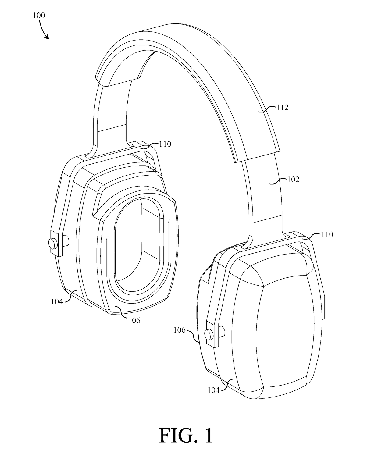
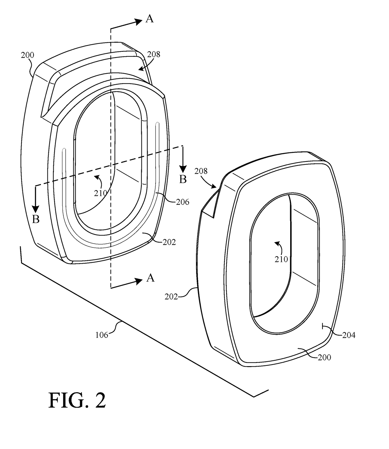
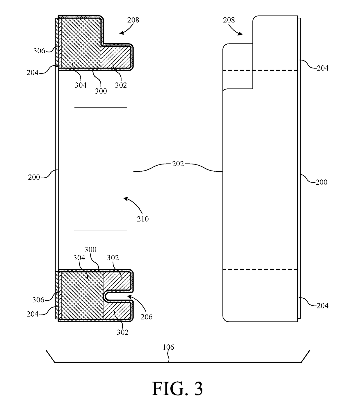
[0028]The present invention overcomes the problems associated with the prior art, by providing ear pads configured to receive portions of articles (e.g., the arms of eyewear, band of a hat, etc.) worn or carried by a user. In the following description, numerous specific details are set forth (e.g., material types, fastening means, size, etc.) in order to provide a thorough understanding of the invention. Those skilled in the art will recognize, however, that the invention may be practiced apart from these specific details. In other instances, details of well-known manufacturing practices (e.g., molding, assembling, adhering, etc.) and components have been omitted, so as not to unnecessarily obscure the present invention.

[0029]In the description that follows, anatomical terms are used to describe positional relationships between features of the headsets / ear pads. The terms are used with the understanding that a headset and attached ear pads are being worn on the head of a user in a n...


PUM


Abstract

A novel ear pad includes a lateral surface and a medial surface. The lateral surface is adapted to be coupled to a headset and the medial surface includes a recess that accommodates the passage of an article between the ear pad and a user's head. In a particular embodiment, the recess is contoured to receive an eyeglass temple. In another embodiment, an ear pad includes an annular wall having an inferior portion and a superior portion wherein the wall thickness of the inferior portion is greater than the wall thickness of the superior portion.

Description

RELATED APPLICATIONS[0001]This application claims the benefit of co-pending U.S. Provisional Patent Application No. 62 / 549,347, filed on Aug. 23, 2017, by the same inventor, which is incorporated herein by reference in its entirety. This application is also a continuation in part of co-pending U.S. Design patent application Ser. No. 29 / 641,499, filed on Mar. 22, 2018, by the same inventor, which is incorporated herein by reference in its entirety.BACKGROUND OF THE INVENTIONField of the Invention[0002]This invention relates generally to headsets, and more particularly to ear pads configured to accommodate eyewear, headwear, or other articles worn or carried by a user.Description of the Background Art[0003]Ear pads are essential to the comfort of various types of headsets such as, for example, audio headphones, sound-dampening ear muffs, noise canceling headsets, etc. One challenge in manufacturing and designing headsets is achieving a universal fit that will provide comfort to all us...

Claims


Application Information

Patent Timeline
Patent Type & Authority Applications(United States)
IPC IPC(8): H04R1/10
CPCH04R1/105H04R1/1008H04R1/1066H04R1/1058
Inventor BRACE, NEAL JOHN
Owner BRACE NEAL JOHN
Why Eureka
Try Eureka