Flow Guiding Device for a Fan

a technology of flow guiding and fan, which is applied in the direction of non-positive displacement fluid engines, pump components, liquid fuel engine components, etc., can solve the problems of adversely affecting the operation stability of the fan, increasing the weight, and increasing the surface area, so as to reduce the moment of inertia during the operation of the fan, improve the rotational efficiency of the fan, and reduce the effect of structural fatigu

Active Publication Date: 2019-03-07
SUNONWEALTH ELECTRIC MACHINE IND
View PDF2 Cites 6 Cited by
  • Summary
  • Abstract
  • Description
  • Claims
  • Application Information

AI Technical Summary

Benefits of technology

[0020]In the example, the blade is hollow. In this arrangement, the moment of inertia during the operation of the fan can be reduced, improving the rotational efficiency of the fan and reducing the structural fatigue thereof.
[0021]In the example, the blade includes at least one supporting rib therein. In this arrangement, the structural strength of the blade can be increased.
[0022]In the example, a cross section of the flow-guiding portion viewed from the radial direction has a same outline as a cross section of the blade viewed from the radial direction. In this arrangement, the air can have a consistent flow path when flowing through the flow-guiding portion and the blade, stabilizing the rotation.
[0023]In the example, the blade further include an inner end opposite to the free end. The inner end of the blade is configured to connect to a rotor of a motor of a ceiling fan. In this arrangement, the rotational efficiency of the ceiling fan can be improved and the vortex can be reduced.

Problems solved by technology

However, the general fan may generate noise due to a rotating blade strongly cutting through the tip vortex generated by the preceding blade, adversely affecting the operational stability of the fan.
However, the use of such a winglet increases the weight, and the increase in surface area leads to an increased friction.
This lowers the operational efficiency of the blade.

Method used


Image

  • Flow Guiding Device for a Fan
  • Flow Guiding Device for a Fan
  • Flow Guiding Device for a Fan

Examples


Embodiment Construction

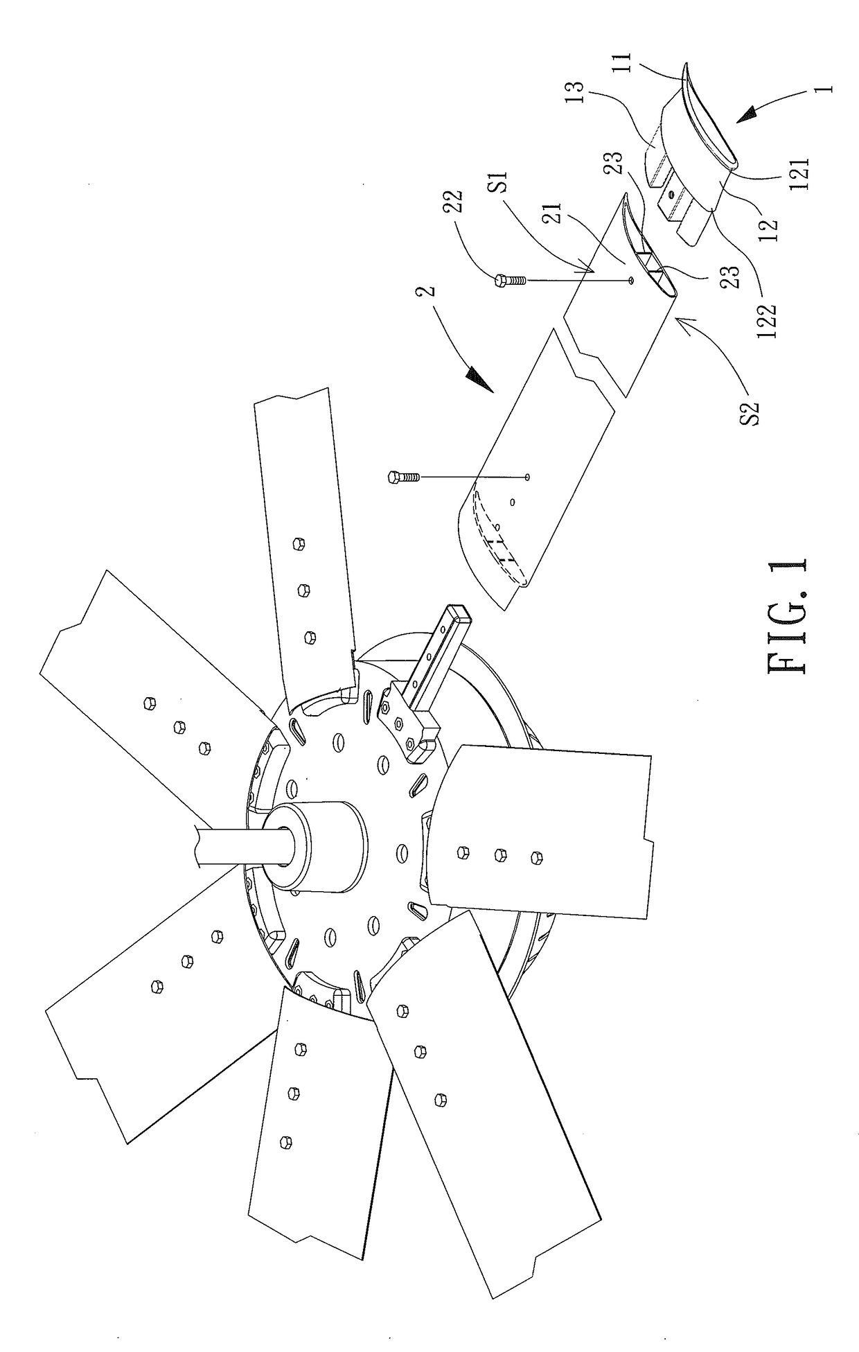
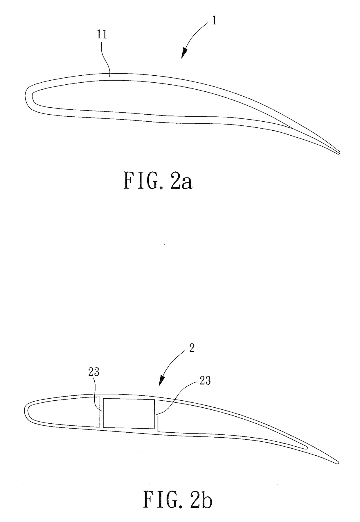
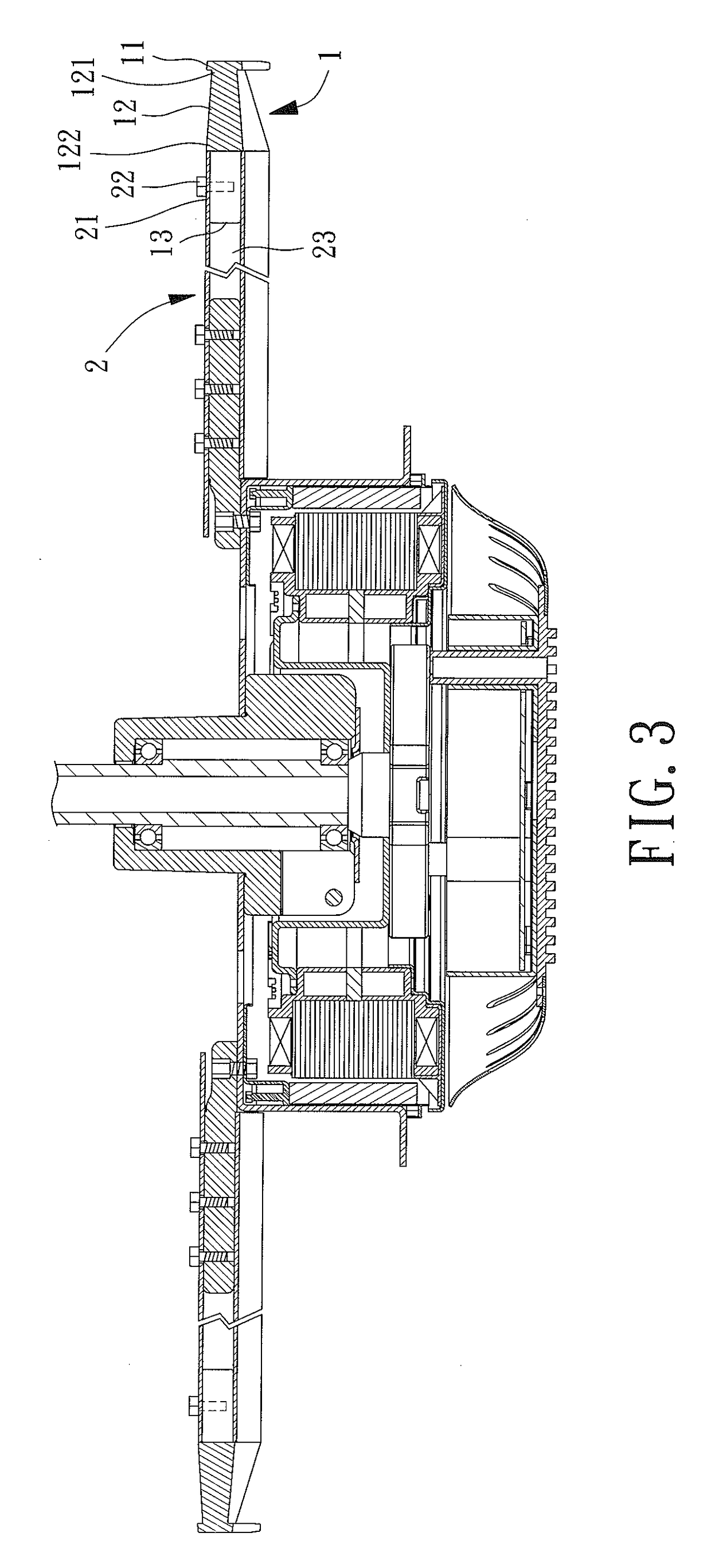
[0035]FIG. 1 shows a flow guiding device for a fan according to a first embodiment of the invention. The flow guiding device includes a plurality of flow-guiding members 1 and a plurality of blades 2. Each blade 2 includes a first end connected to a respective flow-guiding member 1 and a second end connected to a rotor of a motor. The flow-guiding members 1 and the blades 2 jointly rotate with the rotor.

[0036]Each flow-guiding member 1 includes a flow-guiding portion 11, a neck portion 12 and a first coupling portion 13. The neck portion 12 includes a first end 121 connected to a respective flow-guiding portion 11 and a second end 122 connected to the first coupling portion 13.

[0037]Each blade 2 includes a second coupling portion 21 at a tip thereof. The first coupling portion 13 is fixed to the second coupling portion 21. In this embodiment, the first coupling portion 13 includes a plurality of tenons, and the second coupling portion 21 includes a plurality of mortises. The first c...


PUM


Abstract

A flow guiding device includes a flow-guiding member and a blade. The flow-guiding member includes a flow-guiding portion, a neck portion and a first coupling portion. The flow-guiding portion is connected to a first end of the neck portion. The first coupling portion is located at a second end of the neck portion. The flow-guiding portion, the neck portion and the first coupling portion are connected in series in a radial direction. The blade includes a second coupling portion at a free end of the blade. The second coupling portion is coupled with the first coupling portion. The flow-guiding portion has a cross-sectional area smaller than or equal to a cross-sectional area of the blade. A cross-sectional area of the neck portion viewed from the radial direction at the first end is smaller than a cross-sectional area of the neck portion viewed from the radial direction at the second end.

Description

CROSS REFERENCE TO RELATED APPLICATIONS[0001]The application claims the benefit of Taiwan application serial No. 106130185, filed on Sep. 4, 2017, and the entire contents of which are incorporated herein by reference.BACKGROUND OF THE INVENTION1. Field of the Invention[0002]The present invention generally relates to a flow guiding device for a fan and, more particularly, to a flow guiding device for a fan which is able to reduce the vortex at the tips (free ends) of the blades and to improve the rotational efficiency of the fan.2. Description of the Related Art[0003]During the rotation of a blade of a fan, a pressure difference existing between the top and bottom surfaces of the blade causes the air to flow around the tip of the blade from the high-pressure area to the low-pressure area while flowing through the tip of the blade in a tangential direction. Due to the combination of these two types of the air flow patterns, a spiral vortex movement is formed, as is called “tip vortex....

Claims


Application Information

Patent Timeline
Patent Type & Authority Applications(United States)
IPC IPC(8): F04D29/38F04D25/08F04D29/34
CPCF04D29/388F04D25/088F04D29/34F04D29/667F04D29/681F05D2240/307
Inventor HORNG, ALEXYIN, TSO-KUOLIN, CHENG-WEI
Owner SUNONWEALTH ELECTRIC MACHINE IND
Why Eureka
Try Eureka