System and Method for Detecting and Characterizing Defects in a Pipe

a technology of system and method, applied in the direction of magnetic measurement, measurement device, instruments, etc., can solve the problems of pipeline inevitably corroding or otherwise developing defects, metal loss, cracks, etc., and the configuration of magnetic sensors may not be able to distinguish between which defects

Inactive Publication Date: 2019-03-07
DESJARDINS INTEGRITY LTD
View PDF5 Cites 8 Cited by
  • Summary
  • Abstract
  • Description
  • Claims
  • Application Information

AI Technical Summary

Problems solved by technology

Once installed, a pipeline is found to inevitably corrode or otherwise develop defects.
Such defects include metal loss, dents, cracks, and other mechanical damage.
However, the current conventional configuration of magnetic sensors may be unable to discriminate between which defects occur on the internal pipeline surface and which ones occur on the external surface.
Due to the limited range of eddy currents, the eddy current sensor systems reveal only internal defects.
However, typical eddy current sensing systems can consume significant amounts of power and reduce battery life.
Further, such secondary sensor assemblies need additional space and storage, which leads to a higher cost associated with materials, constructing the device, and employing the device inside a pipeline.

Method used


Image

  • System and Method for Detecting and Characterizing Defects in a Pipe
  • System and Method for Detecting and Characterizing Defects in a Pipe
  • System and Method for Detecting and Characterizing Defects in a Pipe

Examples


Embodiment Construction

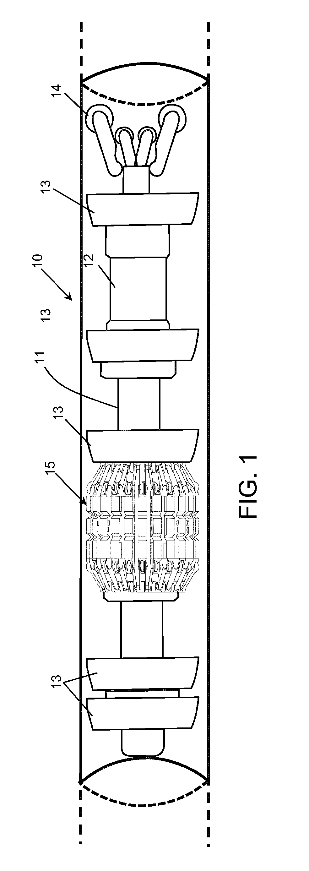
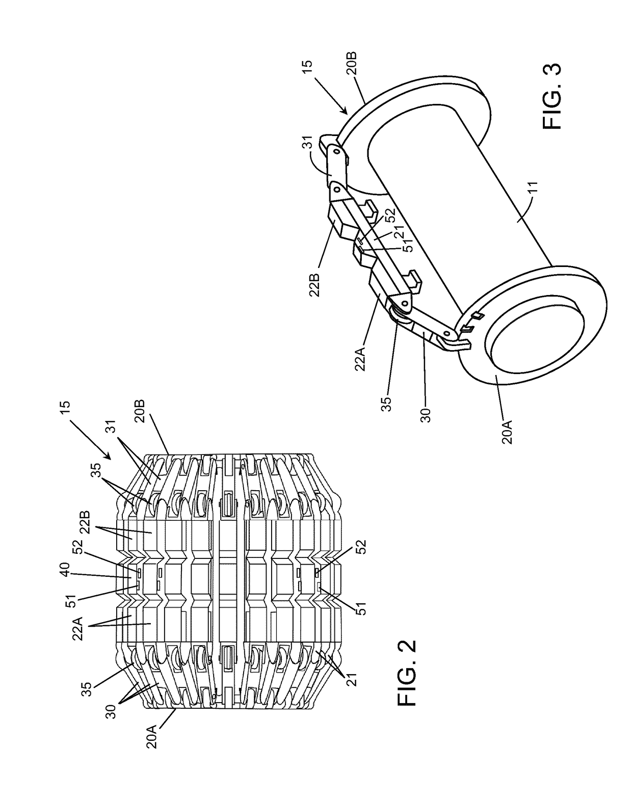
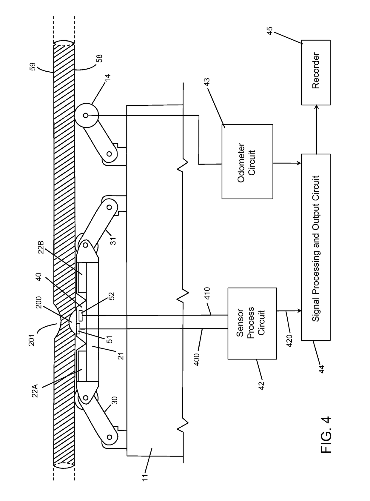
[0022]Referring to FIG. 1, an in-line inspection device 10 used for various pipeline servicing purposes is shown. The in-line inspection device 10 in this example includes a plurality of annular cups 13 affixed around the circumference of the central body 11 which serve to center the inspection device 10 within the pipeline and also to engage the internal pipeline wall so as to trap the flowing fluid, enabling the device to be pushed along the pipeline by the fluid. In the embodiment shown, the in-line inspection device 10 has an instrumentation apparatus 15 that supports magnetic sensor assemblies as discussed below, and a support module 12 that may house the batteries and other electronic and / or recording equipment. Further, the tail end of the device 10 may comprise one or more odometers 14 which measure the distance travelled by the device 10 and provide signals that reveal the location of a pipeline feature.

[0023]The inspection device 10 shown is illustrated by way of example o...


PUM

PropertyMeasurementUnit
polaritiesaaaaaaaaaa
distanceaaaaaaaaaa
dimensionsaaaaaaaaaa

Abstract

An in-line inspection device and methods of operation thereof for identifying and characterizing features of a metallic pipe structure are disclosed. An in-line inspection device with a central body supports an instrument apparatus which includes a plurality of magnetic members to magnetically saturate the pipe, and a plurality of magnetic sensor assemblies to detect magnetic flux leakage signals caused by pipe features. The plurality of magnetic sensor assemblies are positioned such that some are as close as practicable to the internal surface of the pipe, and others are at a predetermined offset distance from the internal surface of the pipe. By analyzing and comparing the outputs of the magnetic sensor assemblies, pipeline features can be identified and characterized.

Description

CROSS-REFERENCE TO RELATED APPLICATION(S)[0001]This application is a continuation of PCT Application No. PCT / CA2017 / 050579 filed on May 15, 2017, which claims priority to U.S. Provisional Patent Application No. 62 / 339,423 filed on May 20, 2016, both incorporated herein by reference.TECHNICAL FIELD[0002]The following relates to systems and methods for detecting and / or characterizing defects in pipes and other tubular members, including pipelines.DESCRIPTION OF THE RELATED ART[0003]Pipelines are often used to transport petroleum products, natural gas, hazardous liquids, and the like. Once installed, a pipeline is found to inevitably corrode or otherwise develop defects. Such defects include metal loss, dents, cracks, and other mechanical damage.[0004]Magnetic flux leakage inspection devices, commonly referring to as “pigs”, are tools that are propelled along a pipeline by the pressure of a fluid in the pipeline, for various servicing purposes. The use of magnetic flux leakage inspecti...

Claims


Application Information

Patent Timeline
Patent Type & Authority Applications(United States)
IPC IPC(8): G01N27/87
CPCG01N27/87G01R33/07
Inventor DESJARDINS, GUY JOSEPH DANIEL
Owner DESJARDINS INTEGRITY LTD
Why Eureka
Try Eureka