
Display device and signal source switching method

a technology of switching method and display device, which is applied in the direction of selective content distribution, electric digital data processing, instruments, etc., can solve the problems of wasting lots of time on detecting inactive signal sources, and the difficulty of effectively switching signal sources for usb type-c connectors, etc., and achieves the effect of easily and quickly switching signal sources

Active Publication Date: 2019-03-07
QISDA CORP
View PDF1 Cites 11 Cited by
  • Summary
  • Abstract
  • Description
  • Claims
  • Application Information

AI Technical Summary

Benefits of technology

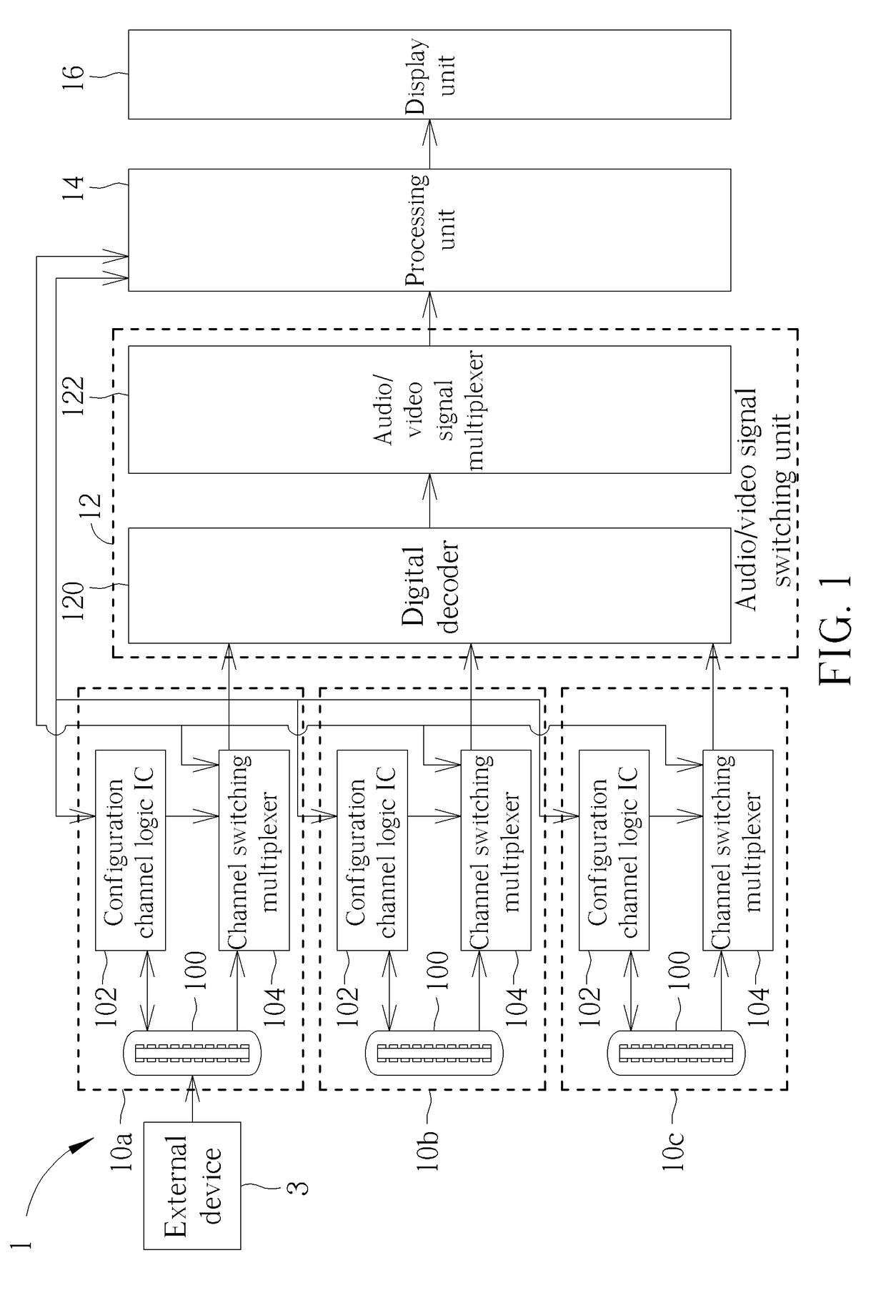
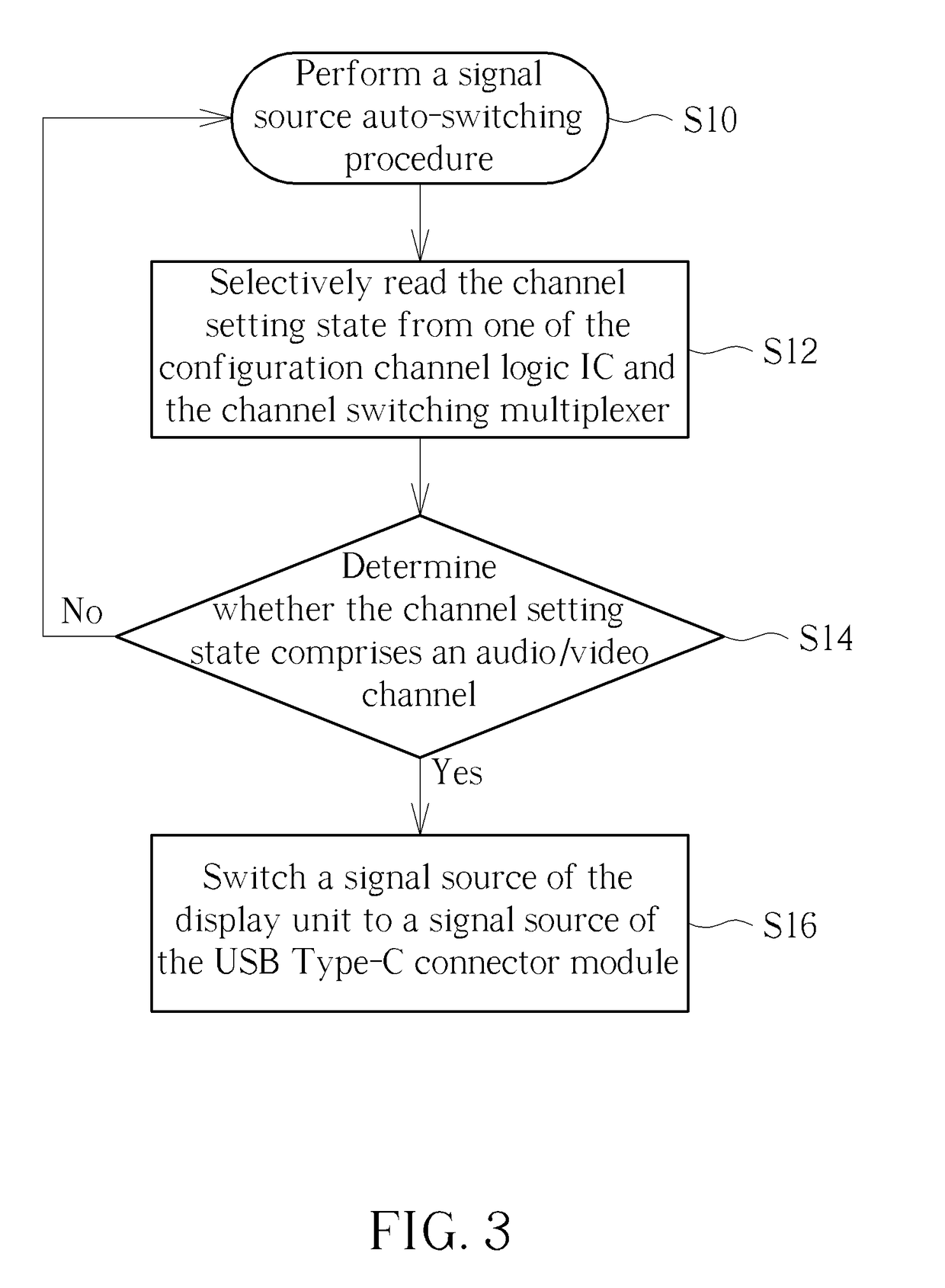
The patent text describes a technology that allows an external device to be connected to a display device through a USB Type-C connector. When the external device is connected, the display device's configuration channel logic IC communicates with the external device through the connector's pin to determine the channel settings. The processing unit then reads the channel settings from either the logic IC or a channel switching multiplexer, and determines if it's the audio / video channel. If it is, the processing unit controls the audio / video switching unit to switch the display device's signal source to the external device's signal source through the USB Type-C connector module. This allows for easy and fast switching between external devices and the display device's audio / video channel.

Problems solved by technology

However, the aforesaid manner wastes lots of time on detecting inactive signal source.
Accordingly, how to switch signal source effectively for the USB Type-C connector has become a significant issue.

Method used


Image

  • Display device and signal source switching method
  • Display device and signal source switching method
  • Display device and signal source switching method

Examples


Embodiment Construction

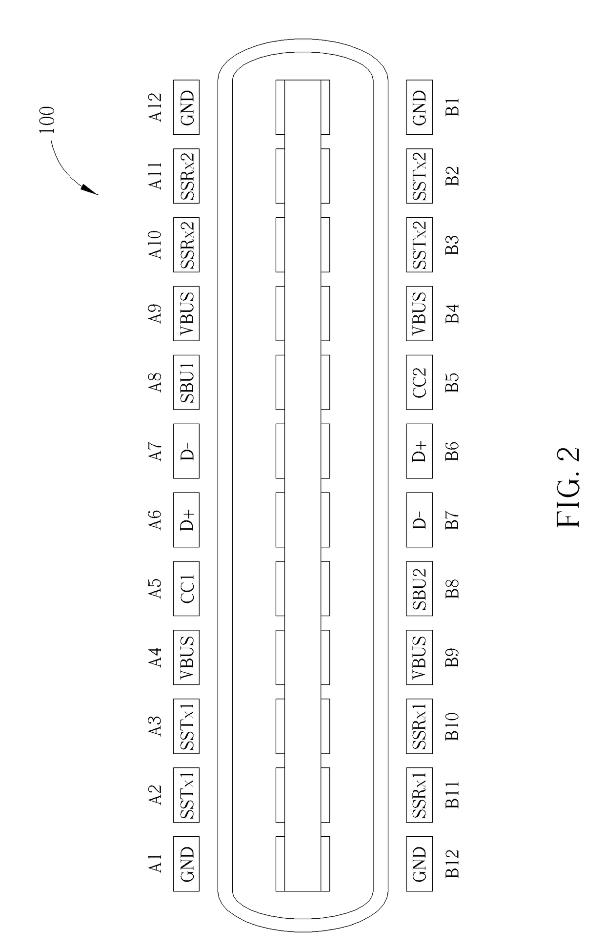
[0018]Referring to FIG. 1, FIG. 1 is a functional block diagram illustrating a display device 1 according to an embodiment of the invention. As shown in FIG. 1, the display device 1 comprises three USB Type-C connector modules 10a-10c, an audio / video signal switching unit 12, a processing unit 14, and a display unit 16. Each of the USB Type-C connector modules 10a-10c comprises a USB Type-C connector 100, a configuration channel logic IC 102, and a channel switching multiplexer 104, wherein the USB Type-C connector 100 is electrically connected to the configuration channel logic IC 102 and the channel switching multiplexer 104, and the configuration channel logic IC 102 is electrically connected to the channel switching multiplexer 104. The audio / video signal switching unit 12 is electrically connected to the channel switching multiplexer 104. The processing unit 14 is electrically connected to the configuration channel logic IC 102, the channel switching multiplexer 104, and the au...


PUM


Abstract

A display device includes a USB Type-C connector module, an audio / video signal switching unit, a processing unit, and a display unit. The USB Type-C connector module includes a USB Type-C connector, a configuration channel logic IC, and a channel switching multiplexer. The processing unit selectively reads a channel setting state from one of the configuration channel logic IC and the channel switching multiplexer and determines whether the channel setting state includes an audio / video channel. When the processing unit determines that the channel setting state includes the audio / video channel, the processing unit controls the audio / video switching unit to switch a signal source of the display unit to a signal source of the USB Type-C connector module.

Description

BACKGROUND OF THE INVENTION1. Field of the Invention[0001]The invention relates to a display device and a signal source switching method and, more particularly, to a display device and a signal source switching method capable of switching signal source automatically.2. Description of the Prior Art[0002]A display device always comprises lots of input connectors with identical or different signal formats, such as audio / video (AV) connector, separate video (S-Video) connector, component video connector, Video Graphics Array (VGA) connector, Digital Visual Interface (DVI) connector, High Definition Multimedia Interface (HDMI) connector, DisplayPort (DP) connector, Universal Serial Bus (USB) Type-C connector, and so on. As the input connector increases, a user has to spend much time to switch a signal source of a display panel to a desired signal source. Currently, the prior art switches the signal source of each input connector one by one, so as to detect whether an active signal exists...

Claims


Application Information

Patent Timeline
Patent Type & Authority Applications(United States)
IPC IPC(8): H04N21/2389H04N21/2368
CPCH04N21/2389H04N21/2368H04N2201/0051G06F13/126H04N21/43632
Inventor LIAO, CHIEN-NAN
Owner QISDA CORP
Learn More