Floor arrangement for a cabin of a vehicle

a technology for vehicles and cabins, applied in the field of floor arrangement for vehicles, to achieve the effect of improving the rigidity of the entire fuselage structure of aircra

Active Publication Date: 2019-03-14
AIRBUS OPERATIONS GMBH
View PDF0 Cites 5 Cited by
  • Summary
  • Abstract
  • Description
  • Claims
  • Application Information

AI Technical Summary

Benefits of technology

[0020]According to a development, a further carrier plate can furthermore be provided. The further carrier plate can be designed identically to the carrier plate. The two carrier plates can be arranged next to each other transversely with respect to the longitudinal direction of the floor arrangement. The fastening rows and the reinforcing notches of the further carrier plate can be oriented rotated by 90° with respect to the fastening rows and the reinforcing notches of the carrier plate in such a manner that the fastening rows and the reinforcing notches of the two carrier plates converge in a V-shaped manner. By this means, the floor arrangement is divided into a left and a right half, which halves are oriented at an opposed angle. The floor arrangement can therefore be arranged in such a manner that a passenger aircraft, for example a commercial aircraft with only a single cabin aisle, i.e., a single aisle aircraft, is separated at a center line. By this means, it is not only possible for the entire floor of the aircraft to be assembled, for example, with a 1″ grid pattern. Furthermore, the rigidity of the entire fuselage structure of the aircraft can be improved by the carrier plates being connected fixedly to cross members of the primary structure of the aircraft, for example via longitudinally oriented bearers, such that the cross members are subjected to a tensile and / or compressive stress depending on orientation in the event of an impact or a knock.

Problems solved by technology

Secondly, the reinforcing notches act to a certain extent as spacers via which an installation space is created for the installation of fastening means in the fastening perforations.

Method used


Image

  • Floor arrangement for a cabin of a vehicle
  • Floor arrangement for a cabin of a vehicle

Examples


Embodiment Construction

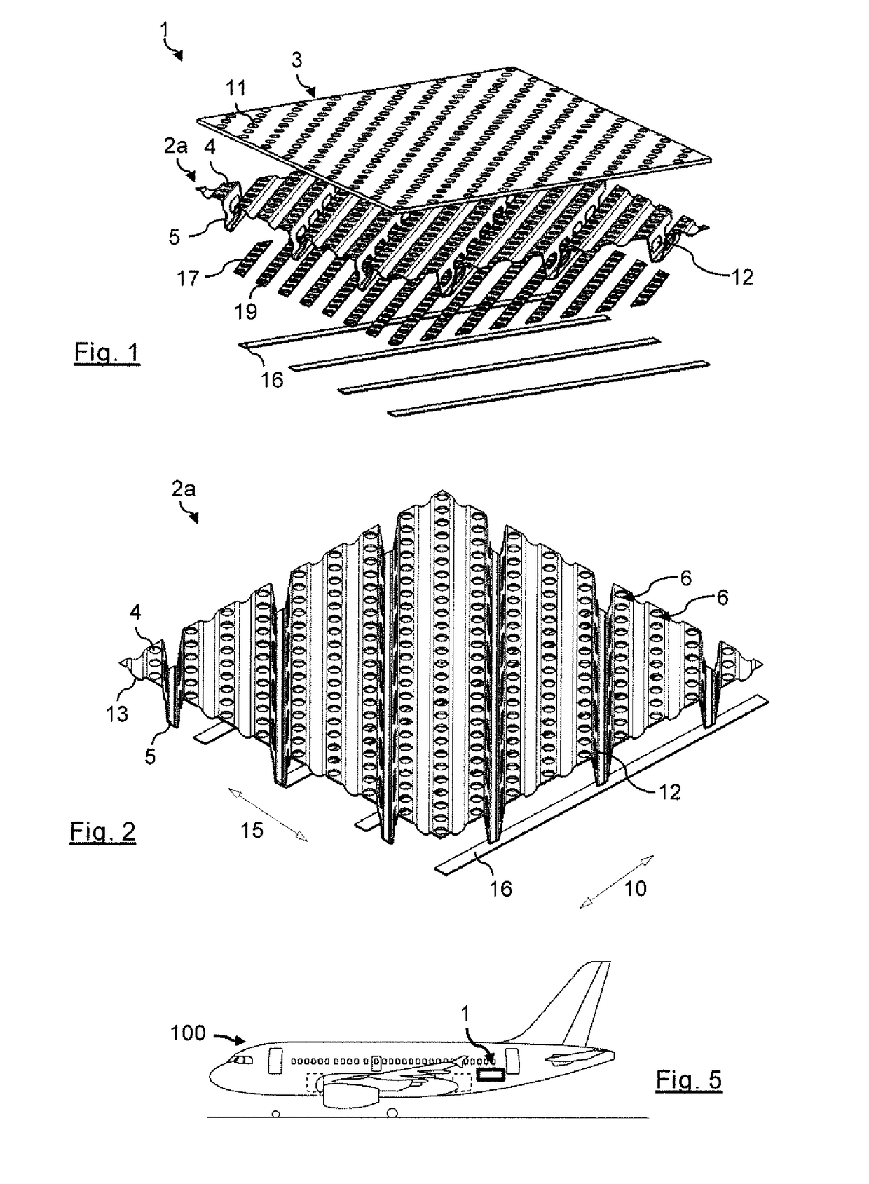
[0030]FIG. 1 shows a schematic exploded view of a floor arrangement 1 according to an embodiment of the invention. FIG. 5 shows a schematic side view of an aircraft 100, for example a passenger aircraft with just a single cabin aisle, i.e., a single aisle aircraft, with the floor arrangement 1 from FIG. 1.

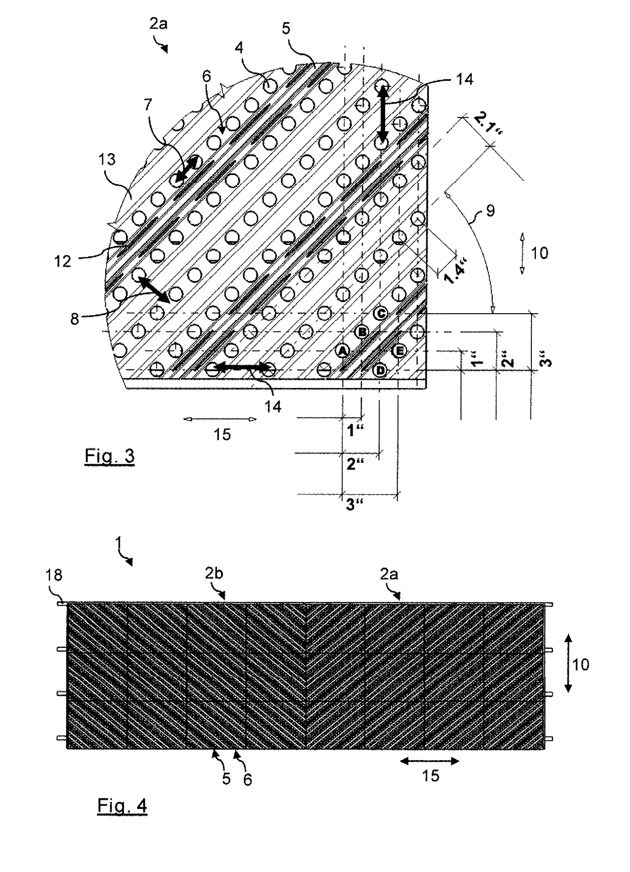
[0031]The floor arrangement 1 comprises a carrier plate 2a and a floor panel 3 which is arranged on the carrier plate 2a. FIG. 2 shows a schematic perspective view of a carrier plate 2a from the floor arrangement 1 from FIG. 1. FIG. 3 adds hereto a schematic top view to the carrier plate 2a from FIG. 2. The carrier plate 2a is formed with a multiplicity of first fastening perforations 4, for example holes, and a multiplicity of reinforcing notches 5 which are arranged and designed in a manner corresponding to a wave-like shape (see further below). The floor panel 3 is correspondingly formed with a multiplicity of second fastening perforations 11. During the installation of the floo...


PUM

PropertyMeasurementUnit
angleaaaaaaaaaa
perforation distanceaaaaaaaaaa
transverse distanceaaaaaaaaaa

Abstract

A floor arrangement for a cabin of a vehicle, in particular of an aircraft or spacecraft, comprises a carrier plate formed with a multiplicity of first fastening perforations and a multiplicity of reinforcing notches. The first fastening perforations are arranged one behind another in fastening rows at a uniform longitudinal distance. The fastening rows are oriented parallel at a uniform transverse distance from one another at an angle of orientation of 45° with respect to a longitudinal direction of the floor arrangement. The reinforcing notches run along the angle of orientation in a manner offset with respect to the fastening rows. A floor panel is formed with a multiplicity of second fastening perforations and is arranged above the carrier plate such that the second fastening perforations are arranged above the first fastening perforations to fasten cabin elements through the floor panel to the carrier plate.

Description

CROSS-REFERENCES TO RELATED APPLICATIONS[0001]This application claims the benefit of the the German patent application No. 10 2017 216 077.2 filed on Sep. 12, 2017, the entire disclosures of which are incorporated herein by way of reference.BACKGROUND OF THE INVENTION[0002]The present invention relates to a floor arrangement for a cabin of a vehicle, in particular, of an aircraft or spacecraft.[0003]Although usable in diverse applications, the present invention and the problem on which it is based will be explained in more detail with respect to passenger aircraft. However, the described devices can also be used in different vehicles and in all sectors of the transport industry, for example for road vehicles, for rail vehicles, for aircraft or for watercraft.[0004]At present, floor assemblies are realized in cabins of passenger aircraft by a multiplicity of floor panels being laid together with fastening rails for the attaching of cabin elements. The fastening rails are typically de...

Claims


Application Information

Patent Timeline
Patent Type & Authority Applications(United States)
IPC IPC(8): B64C1/18
CPCB64C1/18B32B3/10B64D2011/0046B32B2605/18B32B3/266B32B3/28B32B3/30B32B5/24B32B7/08B32B15/04B32B2250/02B32B2260/021B32B2260/046B32B2262/101B32B2262/106B32B2307/546B32B2307/732B32B2605/003
Inventor LANGE, ROLANDHEIDTMANN, ANDREAS
Owner AIRBUS OPERATIONS GMBH
Why Eureka
Try Eureka