Cartridge

a cartridge and cartridge technology, applied in the field of cartridge technology, can solve the problems of changing the position of the contact portion of the cartridge, the cartridge is to be rotated or swung, and the printer-side terminal cannot maintain the contact between the contact portion and the contact portion, so as to reduce the maximum variation amount of the contact portion, reduce the leakage of liquid, and reduce the effect of position variation

Inactive Publication Date: 2019-03-21
SEIKO EPSON CORP
View PDF0 Cites 0 Cited by
  • Summary
  • Abstract
  • Description
  • Claims
  • Application Information

AI Technical Summary

Benefits of technology

[0035](2-8) In the cartridge of the above aspect, a center contact portion provided on center in the X direction among the plurality of contact portions may be arranged to intersect with a plane that includes the center axis of the middle liquid supply port and that is perpendicular to the X direction. This configuration reduces a variation in position of the plurality of contact portions.
[0036](2-9) In the cartridge of the above aspect, the plurality of contact portions may be arranged to be symmetric in the X direction with respect to a plane that includes the center axis of the middle liquid supply port and that is perpendicular to the X direction. This configuration reduces a maximum variation amount of the contact portions.
[0037](2-10) In the cartridge of the above aspect, the three or a larger odd number of liquid supply ports may be aligned parallel to the X direction. This configuration maintains the good connection of the liquid supply ports with the liquid supply needles and reduces leakage of the liquid and invasion of the air into the liquid supply needle.
[0038](2-11) The cartridge of the above aspect may further comprise a concave portion provided on the bottom surface at a position closer to the first side surface than the second side surface to receive an apparatus-side projection provided on the carriage. In the cartridge of this aspect, insertion of the apparatus-side projection into the concave portion restricts the motion of the cartridge. Accordingly this configuration suppresses a variation in position of the contact portions and maintains the good contact between the contact portions and the apparatus-side terminal.

Problems solved by technology

This may cause the cartridge to be rotated or swung.
This may displace the position of the contact portions and may fail to maintain the contact between the printer-side terminals and the contact portions.
Moving the cartridge is likely to change the position of the contact portions of the cartridge and fail to maintain the contact between the printer-side terminals and the contact portions.
This configuration increases the possibility that the placement portion collides with the ground or another surface prior to the remaining part when the user or the manufacturer mistakenly drops down the cartridge.
The configuration of the above aspect thus increases the possibility that the circuit board or the storage device is purposely broken when the cartridge is dropped down.
This reduces the possibility of deformation of the protruded surface portion and reduces the possibility of deformation of the engagement member and displacement of the locking position.

Method used


Image

  • Cartridge
  • Cartridge
  • Cartridge

Examples


first embodiment

[0092]A. First Embodiment

[0093]A-1. General Configuration of Liquid Ejection Apparatus

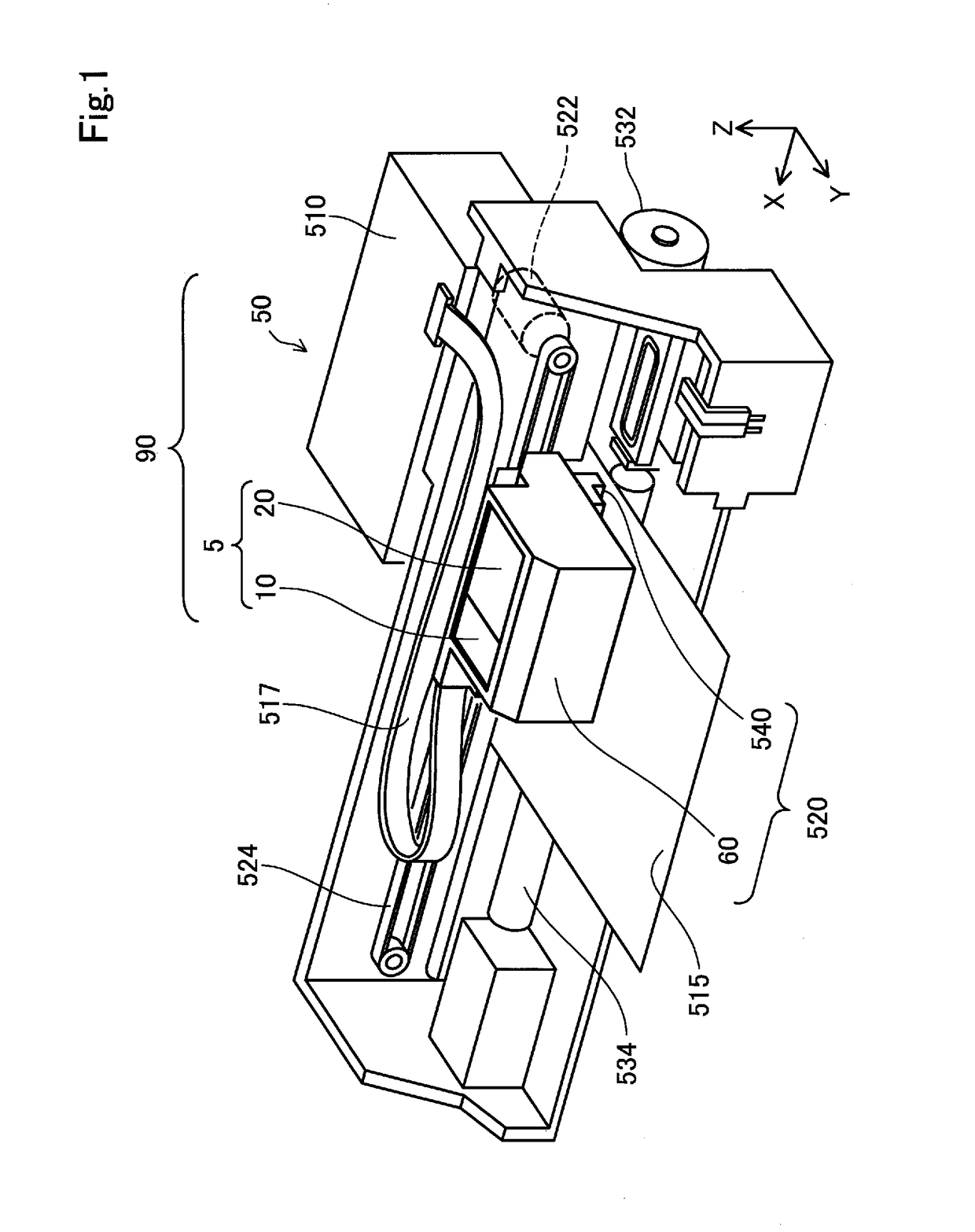
[0094]FIG. 1 is a perspective view illustrating the configuration of a liquid ejection system 90. FIG. 1 illustrates X, Y and Z axes that are orthogonal to one another. The X, Y and Z axes in FIG. 1 correspond to X, Y Z axes in the other drawings. The X, Y and Z axes are provided in subsequent drawings as needed basis. A direction along the X axis is expressed as an X direction, a direction along the Y axis is expressed as a Y direction, and a direction along the Z axis is expressed as a Z direction. One direction of the X direction is expressed as +X direction, and the other direction of the X direction is expressed as −X direction. One direction of the Y direction is expressed as +Y direction, and the other direction of the Y direction is expressed as −Y direction. One direction of the Z direction is expressed as +Z direction, and the other direction of the Z direction is expressed as −Z directio...


PUM


Abstract

An object is to provide a technique that maintains good contact between apparatus-side terminals and contact portions in a second cartridge configured to contain multiple different types of inks. In the cartridge, a center contact portion provided on center in an X direction among a plurality of contact portions is arranged to intersect with a first center plane. Part of the plurality of contact portions is placed in a range where a cartridge-side engagement portion is located, in the X direction. An engagement center is provided between the first center plane and a second center plane.

Description

CROSS REFERENCE TO RELATED APPLICATIONS[0001]The present application is based on, and claims priority from JP Application Serial Number 2017-180091, filed on Sep. 20, 2017, the disclosure of which is hereby incorporated by reference herein in its entirety.BACKGROUND1. Technical Field[0002]The present disclosure relates to technology of a cartridge.2. Related Art[0003]There is a known technique to supply inks to a printer using two different types of cartridges (as described in, for example, JP 2003-520711A, JP 2014-233928A, JP 2015-160314A, JP 2007-276495A, and WO 99 / 59823). A first cartridge that is one of the two different types of cartridges contains one type of ink (for example, black ink). A second cartridge that is the other of the two different types of cartridges contains, for example, multiple different types of inks (for example, yellow, cyan and magenta inks). Each of the two different types of cartridges is provided with contact portions configured to come into contact w...

Claims


Application Information

Patent Timeline
Patent Type & Authority Applications(United States)
IPC IPC(8): B41J2/175B41J2/21
CPCB41J2/1753B41J2/1752B41J2/17546B41J2/17553B41J2/2103B41J2/17509B41J2/17513B41J2/17523B41J2/17556B41J2/17566B41J2002/17569
Inventor FUKASAWA, NORIYUKIISHIZAWA, TAKUMIZUTANI, TADAHIROOYA, SHUN
Owner SEIKO EPSON CORP
Why Eureka
Try Eureka