Sealed battery

a sealed battery technology, applied in the field of sealed batteries, can solve problems such as inconsistency in sealing performance of sealed batteries

Active Publication Date: 2019-11-19
TOYOTA JIDOSHA KK
View PDF22 Cites 0 Cited by
  • Summary
  • Abstract
  • Description
  • Claims
  • Application Information

AI Technical Summary

Benefits of technology

[0009]The disclosure provides a sealed battery with a structure that makes sealing performance of an insulating member consistent in a case where a connecting portion provided in a collector terminal member goes through a through hole provided in a lid member in the sealing battery.
[0016]Because of this, when the other end is crimped, the cylindrical portion is centered with respect to the connecting portion, thereby making it possible to align the position of the central axis of the connecting portion and the position of the central axis of the cylindrical portion. Thus, it is possible to correct variation in positions when the cylindrical portion is assembled, and accurately position the cylindrical portion with respect to the connecting portion. Further, because of this, it is possible to prevent variation in compressibility.
[0018]With this sealed battery, it is possible to achieve consistent sealing performance of the insulating member in the case where the connecting portion provided in the collector terminal member goes through the through hole provided in the lid member.

Problems solved by technology

In JP 2014-049396 A, when there are manufacturing errors in height and position of the projection provided on the collector terminal member side and height and position of the projection provided in the lid member in each product, there is a concern that the recessed amounts can vary, which can cause inconsistent sealing performance of the sealed battery.

Method used


Image

  • Sealed battery
  • Sealed battery
  • Sealed battery

Examples


first embodiment

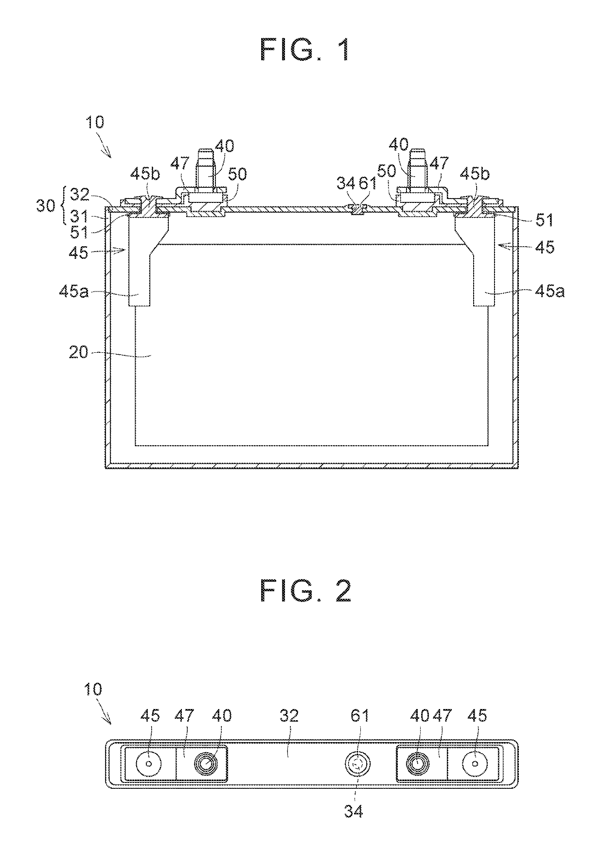
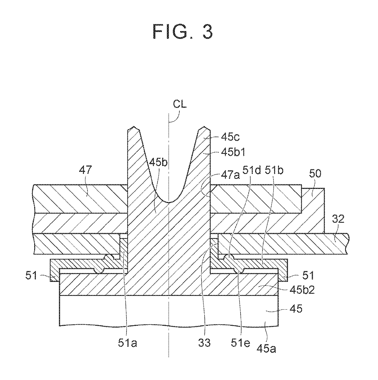
[0039]A structure of a sealed battery 10 according to the embodiment is explained with reference to FIG. 1 to FIG. 3. FIG. 1 is a longitudinal sectional view of the internal structure of the sealed battery 10, FIG. 2 is a plan view of the sealed battery 10, and FIG. 3 is a longitudinal sectional view of a state before crimping in a through hole through which a connecting terminal passes. The sealed battery 10 is a nonaqueous electrolyte secondary battery such as a lithium ion secondary battery, and a plurality of the sealed batteries 10 are combined in series, thus forming a battery pack, and are mounted on a hybrid vehicle and so on. The battery pack serves as a power source of a hybrid vehicle, together with an internal combustion engine such as a gasoline engine and a diesel engine. However, the structure of the sealed battery 10 described below is not limited to a nonaqueous electrolyte secondary battery.

[0040]With reference to FIG. 1 and FIG. 2, the sealed battery 10 includes ...

second embodiment

[0080](Second Embodiment)

[0081]Next, with reference to FIG. 17, a shape of an insulating member 51A according to the second embodiment is explained. FIG. 17 is a view of a sectional shape of the insulating member 51A.

[0082]In comparison with the structure of the insulating member 51 according to the first embodiment, only the second projecting portion 51e is formed, and the first projecting portion 51d is not formed in an insulating member 51A according to this embodiment. As a substitute for the first projecting portion 51d, a first projecting portion 32a is provided in a lid member 32, projecting towards a flat plate portion 51b side of the insulating member 51A.

[0083]Also, the peak position P1 of the first projecting portion 32a is closer to the central axis CL of a connecting portion 45b1 than the peak position P2 of the second projecting portion 51e.

[0084]In this insulating member 51A, although it is necessary to form the first projecting portion 32a in the lid member 32, it i...

third embodiment

[0085](The Third Embodiment)

[0086]Next, with reference to FIG. 18, a shape of an insulating member 51B according to the third embodiment is explained. FIG. 18 is a view of a sectional shape of the insulating member 51B.

[0087]In comparison with the structure of the insulating member 51 according to the first embodiment, only the first projecting portion 51d is formed, and the second projecting portion 51e is not formed in the insulating member 51B according to this embodiment. As a substitute of the second projecting portion 51e, a second projecting portion 45p is provided in a flange portion 45b2, projecting towards a flat plate portion 51b side of the insulating member 51B.

[0088]Also, the peak position P1 of the first projecting portion 51d is closer to the central axis CL of a connecting portion 45b1 than the peak position P2 of the second projecting portion 45p.

[0089]In this insulating member 51B, although it is necessary to form the second projecting portion 45p in the flange po...


PUM

PropertyMeasurementUnit
shapeaaaaaaaaaa
insulatingaaaaaaaaaa
electric poweraaaaaaaaaa

Abstract

Provided is a sealed battery, which includes an insulating member arranged between a lid member and a collector terminal member. The insulating member includes a cylindrical portion that is positioned between a through hole and a connecting portion and surrounds the connecting portion, and a flat plate portion positioned between the lid member and the flange portion, and the flat plate portion has a first projecting portion projecting towards the lid member side, and a second projecting portion projecting towards the flange portion side. In a sectional view taken along a virtual plane including a central axis of the connecting portion, a peak of the first projecting portion is provided at a position closer to the central axis than a peak position of the second projecting portion.

Description

INCORPORATION BY REFERENCE[0001]The disclosure of Japanese Patent Application No. 2016-027098 filed on Feb. 16, 2016 including the specification, drawings and abstract is incorporated herein by reference in its entirety.BACKGROUND[0002]1. Technical Field[0003]The disclosure relates to a sealed battery.[0004]2. Description of Related Art[0005]Japanese Patent Application Publication No. 2014-049396 (JP 2014-049396 A) discloses a sealed battery in which a battery element is provided inside a sealed case. In JP 2014-049396 A, a connecting portion is used in a collector terminal member that is connected with the internal battery element. The connecting portion passes through a lid member that structures the case, and is used for exchanging electric power with outside.[0006]A technology is employed where, in a through hole provided in the lid member, an insulating member is provided as a seal member between the connecting portion and the lid member, and the insulating member is compressed...

Claims


Application Information

Patent Timeline
Patent Type & Authority Patents(United States)
IPC IPC(8): H01M2/06H01M2/30H01M2/04H01M10/0525H01M2/10H01M50/528H01M50/15H01M50/152H01M50/176H01M50/179H01M50/186H01M50/209H01M50/213H01M50/55H01M50/553H01M50/559H01M50/562
CPCH01M2/30H01M2/1077H01M2/06H01M10/0525H01M2/043H01M2220/20H01M10/058H01M50/176H01M50/179H01M50/553H01M50/152H01M50/186H01M50/15H01M50/562H01M50/55H01M50/559H01M50/209H01M50/213Y02E60/10Y02P70/50H01M10/052H01M50/528
Inventor YONEDA, KOSHIRO
Owner TOYOTA JIDOSHA KK
Why Eureka
Try Eureka