
Work vehicle and control method for work vehicle

a technology for work vehicles and control methods, applied in mechanical devices, servomotors, transportation and packaging, etc., can solve the problem of the upper limit of the steering angular velocity of the vehicle body, and achieve the effect of suppressing unnecessary operations, reducing the toll on the body, and suppressing unnecessary operations

Active Publication Date: 2019-03-21
KOMATSU LTD
View PDF8 Cites 3 Cited by
  • Summary
  • Abstract
  • Description
  • Claims
  • Application Information

AI Technical Summary

Benefits of technology

The patent is about a system that allows operators to know when they are approaching or reaching their maximum steering angle. This system uses a threshold value to determine when the operator's hand is close to its maximum limit. This helps to prevent unnecessary movement and reduces the strain on the operator's body. The system can also provide information through vibrations. Overall, the system improves the efficiency and safety of steering operations.

Problems solved by technology

However, there is an upper limit to the steering angular velocity of the vehicle body, and the position where the steering angular velocity reaches its upper limit is provided ahead of the restricted position of the joystick lever.
Therefore, even though the steering angular velocity has reached the upper limit, the operator may not be aware of this, and may vainly attempt to operate the joystick lever to the restricted position.

Method used


Image

  • Work vehicle and control method for work vehicle
  • Work vehicle and control method for work vehicle
  • Work vehicle and control method for work vehicle

Examples


embodiment 1

1. Configuration

1-1. Overview of Wheel Loader Configuration

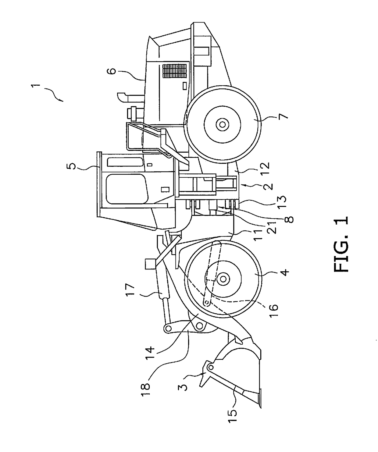
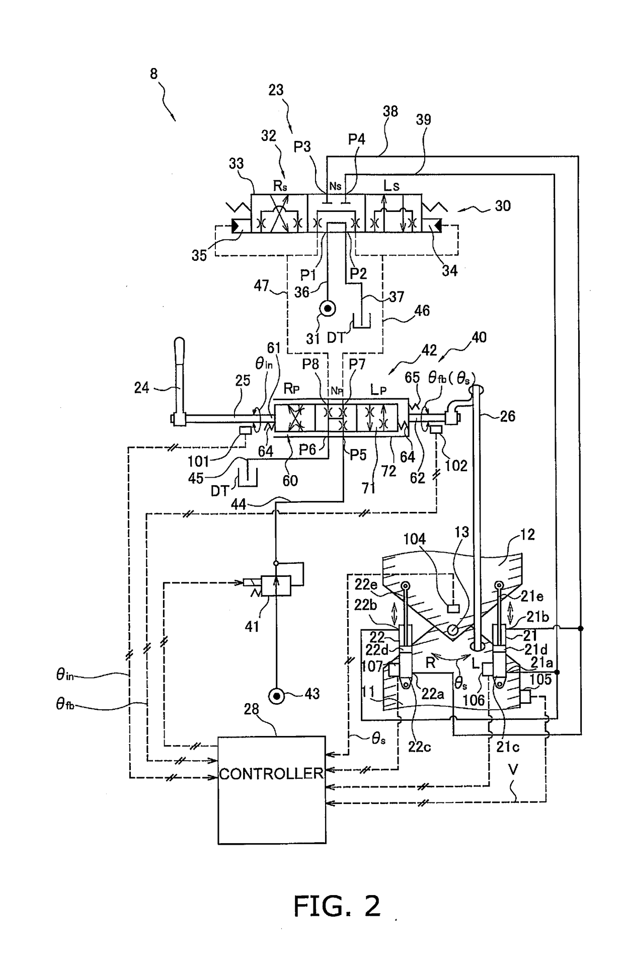
[0062]FIG. 1 is a simplified diagram of the configuration of a wheel loader 1 in this embodiment. The wheel loader 1 in this embodiment comprises a body frame 2, a work implement 3, a pair of front tires 4, a cab 5, an engine compartment 6, a pair of rear tires 7, and a steering operation device 8 (see FIG. 2 (discussed below)).

[0063]The wheel loader 1 uses the work implement 3 to load earth and perform other such work.

[0064]The body frame 2 is what is called an articulated type, and has a front frame 11, a rear frame 12, and a connecting shaft 13. The front frame 11 is disposed ahead of the rear frame 12. The connecting shaft 13 is provided in the center in the vehicle width direction, and links the front frame 11 and the rear frame 12 so that they can pivot relative to each other. The front tires 4 are mounted on the left and right sides of the front frame 11. The rear tires 7 are mounted on the left and right sides of the...

embodiment 2

[0195]The basic configuration of the wheel loader in Embodiment 2 is the same as that in Embodiment 1, but the configuration of the controller and the angular velocity corresponding value sensing unit for sensing information related to the steering angular velocity is different. More specifically, with the wheel loader 1 in Embodiment 1, it is detected that the steering angular velocity is close to its upper limited by detecting that the discharge flow rate of the steering pump 31a has reached the threshold flow rate on the basis of the rotational speed of the engine 50 and the swash plate angle, but in Embodiment 2 it is detected that the discharge amount of the steering pump 31a has reached the threshold flow rate on the basis of the rotational speed of the engine 50 and the LS pressure. Therefore, Embodiment 2 will be described by focusing on what is different from Embodiment 1. In Embodiment 2, those components that are the same as in Embodiment 1 will be numbered the same.

1. Co...

embodiment 3

[0212]The basic configuration of the wheel loader Embodiment 3 is the same as in Embodiment 1, but the configuration of the controller and the angular velocity corresponding value sensing unit for sensing information related to the steering angular velocity is different. More specifically, with the wheel loader 1 in Embodiment 1, it is detected that the steering angular velocity is close to its upper limited by detecting that the discharge flow rate of the steering pump 31a has reached the threshold flow rate on the basis of the rotational speed of the engine 50 and the swash plate angle, but in Embodiment 3 it is detected that the steering angular velocity is close to its upper limit on the basis of the rotational speed of the engine 50 and the deviation angle α. Therefore, Embodiment 3 will be described by focusing on what is different from Embodiment 1. In Embodiment 3, those components that are the same as in Embodiment 1 will be numbered the same.

1. Configuration

1-1. Angular Ve...


PUM


Abstract

A work vehicle includes a hydraulic actuator, a hydraulic pump, an operation member, a control valve, an angular velocity corresponding value sensing unit, a notification component, and a controller. The actuator changes a steering angle based on a supplied fluid. The pump supplies fluid to the actuator. The operation member is operated by an operator when the steering angle is changed. The valve controls flow of fluid supplied from the pump to the actuator based on an amount the operation member is operated. The sensing unit senses a corresponding value corresponding to a steering angular velocity changed based on the flow of fluid. The notification component notifies that the corresponding value has reached a threshold value preset based on an upper limit of the steering angular velocity. The controller causes the notification component to perform a notification when it is detected that the corresponding value has reached the threshold value.

Description

CROSS-REFERENCE TO RELATED APPLICATIONS[0001]This application is a U.S. National stage application of International Application No. PCT / JP2017 / 030626, filed on Aug. 25, 2017. This U.S. National stage application claims priority under 35 U.S.C. § 119(a) to Japanese Patent Application No. 2016-165944, filed in Japan on Aug. 26, 2016, the entire contents of which are hereby incorporated herein by reference.BACKGROUNDField of the Invention[0002]The present invention relates to a work vehicle and a method for controlling a work vehicle.Background Information[0003]A configuration of an articulated work vehicle has been disclosed in which the steering angle is varied by controlling the flow of fluid supplied to a hydraulic actuator disposed spanning a front frame and a rear frame (see, for example, JP-A H11-105723 and JP-A H11-321664.[0004]The work vehicles in JP-A H11-105723 and JP-A H11-321664 are provided with a steering valve that adjusts the flow of fluid supplied to a hydraulic actua...

Claims


Application Information

Patent Timeline
Patent Type & Authority Applications(United States)
IPC IPC(8): B62D5/26E02F9/20E02F9/22E02F9/26B62D3/14B62D12/00B62D5/087B62D5/12F15B11/16
CPCE02F9/225E02F9/2267E02F9/26B62D3/14F15B2211/605B62D5/087E02F9/2004F15B11/161E02F3/342F15B2211/7107F15B2211/7053B62D12/00B62D5/26B62D5/12B62D5/065B62D5/28B62D6/00E02F9/16E02F9/2296E02F9/2087E02F9/2232
Inventor TAKENAKA, YUITAIKARI, MASANORINAKABAYASHI, MASANOBU
Owner KOMATSU LTD
Learn More