
Drinking cup lid

a technology for drinking cups and lids, which is applied in the field of drinking cup lids, can solve the problems of more laborious use, more difficult to remove the plug from the well or insert the plug into the well, and the plug is more difficult to be removed from the well or inserted into the well, so as to save effort, reduce the friction fit of the plug portion to the drinking opening, and reduce the effect of effor

Active Publication Date: 2019-03-21
CHOU CHEN YU +1
View PDF8 Cites 5 Cited by
  • Summary
  • Abstract
  • Description
  • Claims
  • Application Information

AI Technical Summary

Benefits of technology

The present invention provides a drinking cup lid with a splash proof plug that is easier to use and solves the problem of laborious plug-and-pull. This lid achieves a convenient drinking effect with a center cover, rib ring, vent hole, and snap ring portion. The plug is connected by a flexible strip in a hanging way to the external circumferential edge of the snap ring portion, which is made up of an insert portion, hand-held portion, and insert portion. The plug can be pulled out of the drinking recess with less effort due to the pressing force of the insertion opening, making it an effort-saving plug and pull effect.

Problems solved by technology

The high-strength friction fit ensures that it is more difficult to remove the plug from the well or to insert the plug into the well.
Accordingly, the use is more laborious.
In this case, the plug will be more difficultly removed from the well or inserted into the well.
Meanwhile, the user has to retract the head at a large angle in drinking, thereby causing an uncomfortable drinking position.

Method used


Image

  • Drinking cup lid
  • Drinking cup lid
  • Drinking cup lid

Examples


Embodiment Construction

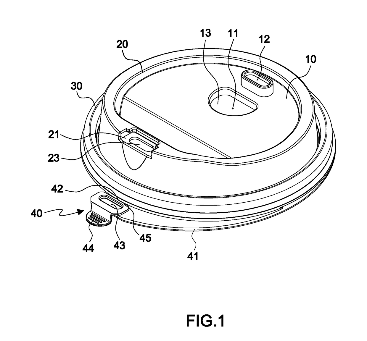
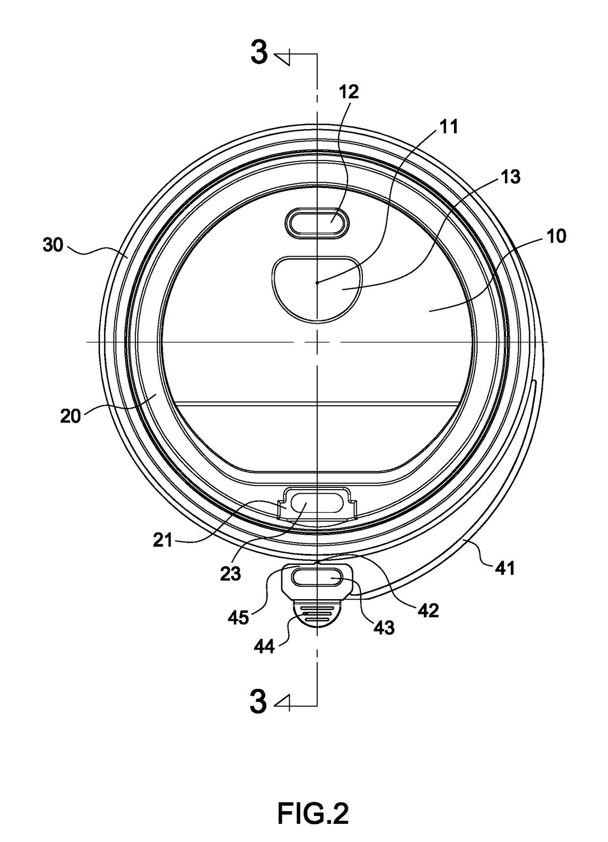
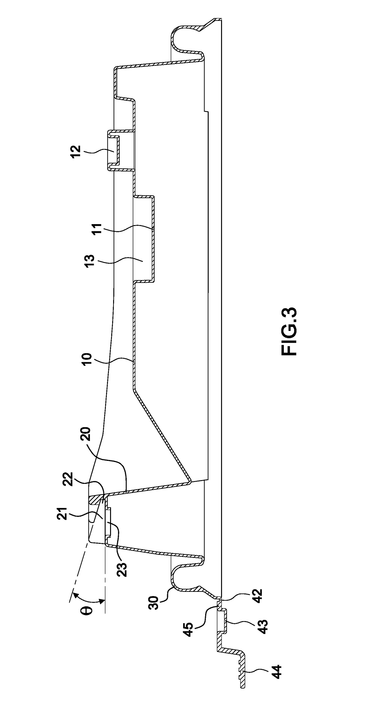
[0022]With reference to FIGS. 1 through 3, a drinking cup lid has a center cover portion 10, a rib ring 20, a vent hole 11, a positioning blind hole 12, a snap ring portion 30, and a plug 40.

[0023]The rib ring 20 is formed in an upwardly tapered way at the external circumferential edge of the center cover portion 10. The rib ring 20 includes a drinking recess 21. The external edge of the drinking recess 21 is open while an insertion opening 22 is disposed at the internal edge thereof The insertion opening 22 has an upward elevation θ from inside to outside. The bottom surface of the drinking recess 21 is provided with a drinking opening 23.

[0024]The vent hole 11 is formed in the center cover portion 10 or in the rib ring 20.

[0025]The positioning blind hole 12 is formed in an upward projecting way at the center cover portion 10 or at the rib ring 20.

[0026]The snap ring portion 30 is formed at the external circumferential edge of the rib ring 20 for a snap fit to the drinking cup.

[002...


PUM


Abstract

A drinking cup lid, comprising: a center cover portion; a rib ring formed at the external circumferential edge of the center cover portion, the rib ring having a drinking recess, the external edge of the drinking recess being open while an insertion opening is disposed at the internal edge thereof, the bottom surface of the drinking recess being provided with a drinking opening; a vent hole formed in the center cover portion or in the rib ring; a snap ring portion formed at the external circumferential edge of the rib ring for a snap fit to the drinking cup; and a plug connected by a flexible strip in a hanging way to the external circumferential edge of the snap ring portion, the plug having a plug portion, a hand-held portion and an insert portion. Before use, the insert portion of the plug is fitted first into the insertion opening. Thereafter, the plug portion is fitted to the drinking opening. In this way, the laborious plug-and-pull problem of the conventional splash proof plug is resolved. As a result, the splash proof plug according to the invention can achieve an effort-saving plug-and-pull effect.

Description

BACKGROUND OF THE INVENTION(a) Field of the Invention[0001]The present invention relates to a drinking cup lid, and more particularly to a plug that prevents the beverage from splashing from the drinking recess and achieves an effort-saving plug and pull effect when fitted to the drinking recess.(b) Description of the Related Art[0002]U.S. Pat. No. 7,954,659 B2 discloses a lid for attachment to a disposable drinking cup. A disc of the drinking cup lid has a well and a plug fits to the well in the friction-fit / snap-fit relationship. The well is provided with a fluid opening. The plug is connected to the peripheral edge of the disc by a pair of support arms such that the plug can be inserted into the well for preventing the beverage from splashing from the well. When the plug is removed from the well, this allows drinking from the top circumferential edge of the well. At the same time, the plug stays in connection with the peripheral edge of the disc by the support arms so that the pl...

Claims


Application Information

Patent Timeline
IPC IPC(8): B65D43/02B65D47/36B65D47/08
CPCB65D43/0218B65D47/36B65D47/0842B65D47/0852B65D2543/00555B65D2543/00046B65D2543/00092B65D2543/00796B65D2543/00518B65D2231/02B65D43/0208B65D47/141B65D47/32B65D2543/00296B65D2543/00509B65D2543/00537B65D2543/0074B65D2543/00027
Inventor CHOU, CHEN-YUCHOU, CHEN-YIN
Owner CHOU CHEN YU
Learn More