Turbine support structure, turbine and gas turbine using the same

Active Publication Date: 2019-03-21
DOOSAN HEAVY IND & CONSTR CO LTD
View PDF0 Cites 5 Cited by
  • Summary
  • Abstract
  • Description
  • Claims
  • Application Information

AI Technical Summary

Benefits of technology

[0011]An object of the present disclosure is to provide to a turbine support structure in which a structure of supporting a turbine casing is configured to be movable when the turbine casing is thermally deforme

Problems solved by technology

Thus, a structure of supporting the turbine casing may be fatigue

Method used


Image

  • Turbine support structure, turbine and gas turbine using the same
  • Turbine support structure, turbine and gas turbine using the same
  • Turbine support structure, turbine and gas turbine using the same

Examples


first embodiment

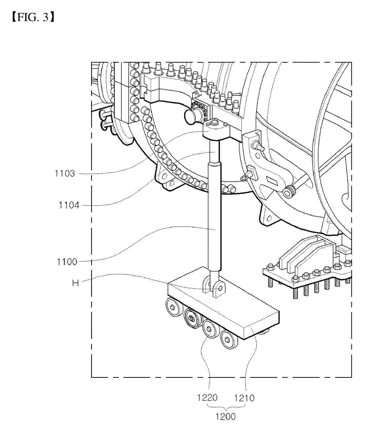
[0058]Referring to FIGS. 3 to 6, the turbine casing support structure in accordance with the present disclosure includes a pair of supports 1100 and a pair of movable units 1200.

[0059]The supports 1100, each having a circular rod shape, are configured to support respective opposite side surfaces of the turbine casing 102b.

[0060]The turbine casing 102b has a structure in which an upper casing 1102a and a lower casing 1102b, each of which has a semi-cylindrical shape, are coupled facing each other. A flange part 1103 protruding outward is formed on each of the junctions between the upper casing 1102a and the lower casing 1102b. An insert hole 1103a is formed in the flange part 1103.

[0061]A bolt part 1104 having an external thread on an outer surface is provided on an upper end of each support 1100. The bolt part 1104 is inserted through the insert hole 1103a of the flange part 1103 and then coupled to the flange part 1103. A nut 1106 is provided on an upper surface of the flange part...

second embodiment

[0069]FIGS. 7 and 8 show a turbine / turbine casing supported by the turbine casing support structure in accordance with the present disclosure.

[0070]Referring to FIGS. 7 and 8, the turbine casing support structure in accordance with the second embodiment of the present disclosure includes a pair of supports 2100 and a pair of movable units 2200.

[0071]The turbine casing support structure in accordance with the second embodiment of the present disclosure is a turbine casing support structure having a structural modification of the movable unit in accordance with the preceding first embodiment.

[0072]In the following description of the configuration of the turbine casing support structure in accordance with the second embodiment of the present disclosure, descriptions of the same components as those of the first embodiment will be omitted, and only a configuration related to the movable unit 2200 different from that of the first embodiment will be explained.

[0073]Each movable unit 2200 i...


PUM


Abstract

A turbine support structure supports a turbine casing and is configured to be movable when the turbine casing is thermally deformed while a gas turbine is operated, thus preventing a fatigue fracture of the turbine casing from occurring. The turbine support structure includes a pair of supports, each having an upper and lower end, for supporting respective opposite side surfaces of the turbine casing at the upper end of either support; and a movable unit installed at the lower end of each support and configured to movably support the lower end of the support. The movable unit is spaced outwardly from the corresponding opposite side surface of the turbine casing, so that the corresponding support inclines toward the turbine casing and is rotatable. The lower end of each support is rotatably coupled to the corresponding movable unit so that the support is rotatable toward an axis of the turbine casing.

Description

CROSS-REFERENCE TO RELATED APPLICATIONS[0001]This application claims the benefit of Korean Patent Application No. 10-2017-0121198, filed on Sep. 20, 2017, in the Korean Intellectual Property Office, the disclosure of which is incorporated herein in its entirety by reference.BACKGROUND OF THE DISCLOSUREField of the Disclosure[0002]Exemplary embodiments of the present disclosure relate to a turbine support structure, a turbine and a gas turbine using the same, and more particularly, to a turbine support structure having an improved turbine casing support structure for coping with thermal deformation of a turbine casing, and a turbine and a gas turbine using the turbine support structure.Description of the Related Art[0003]A turbine is a machine which generates rotating force from impulsive force or reaction force using the flow of compressive fluid such as steam or gas. The turbine is classified into a steam turbine using steam, a gas turbine using high-temperature combustion gas, and...

Claims


Application Information

Patent Timeline
IPC IPC(8): F01D25/28F02C3/04F01D25/26
CPCF01D25/285F02C3/04F01D25/265F05D2220/32F05D2240/90F05D2240/14F05D2260/31F05D2230/642F01D25/28F01D25/243F05D2260/02F16M1/04
Inventor BAE, JIN HOCHOI, JAE HYEONG
Owner DOOSAN HEAVY IND & CONSTR CO LTD
Why Eureka
Try Eureka