Imaging lens
a technology of imaging lens and image, applied in the field of imaging lens, can solve the problems of difficult aberration correction in the peripheral area, inability to obtain proper optical performance, and difficulty in the conventional lens system to realize imaging lens, etc., and achieve the effect of high resolution
- Summary
- Abstract
- Description
- Claims
- Application Information
AI Technical Summary
Benefits of technology
Problems solved by technology
Method used
Image

Examples
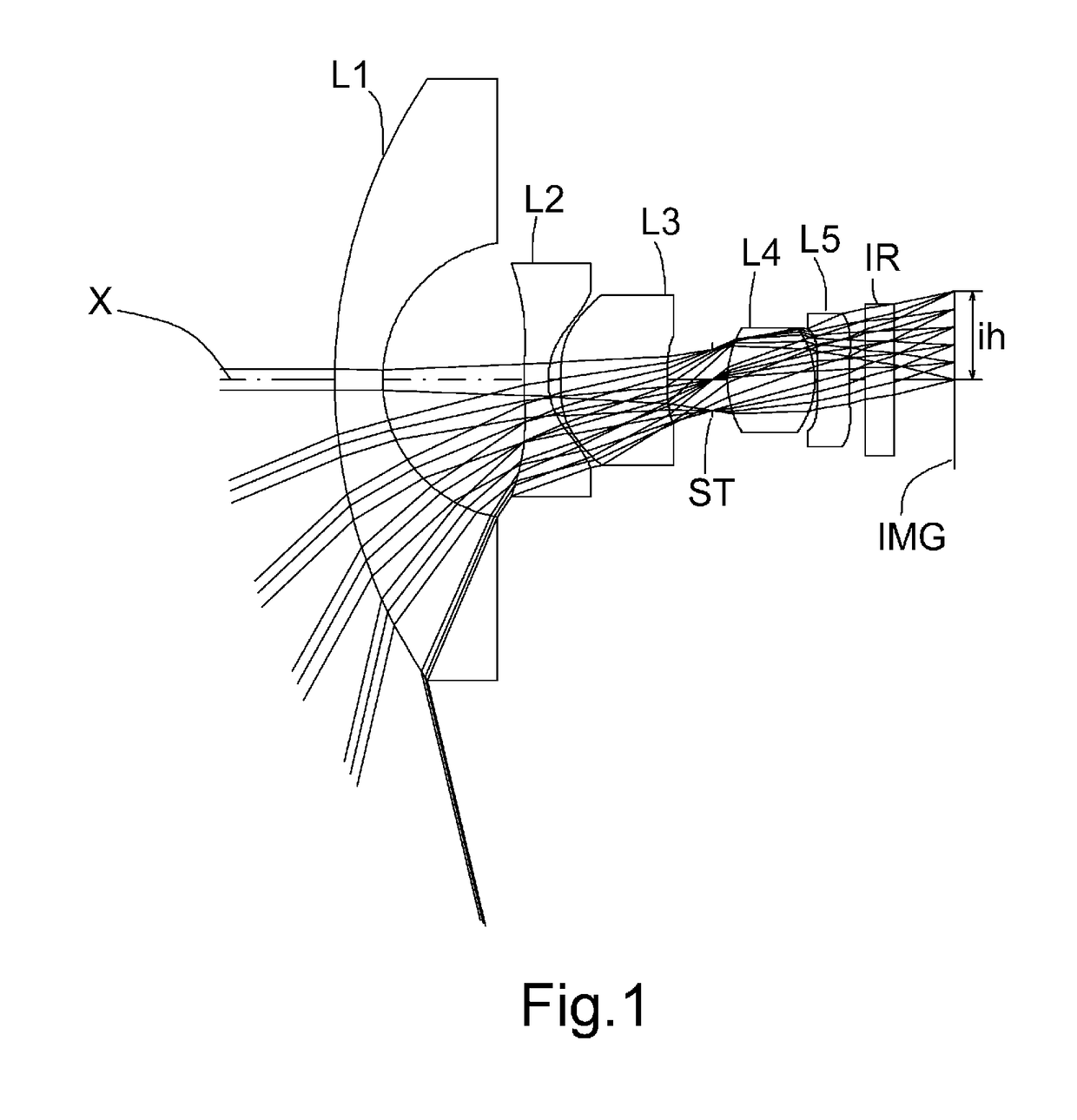
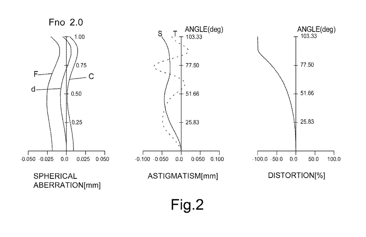
example 1
[0073]The basic lens data is shown below in Table 1.
TABLE 1Example 1Unit mmf = 0.91Fno = 2.0ω(°) = 103.3ih = 1.85TTL = 12.78Surface DataSurfaceCurvatureSurfaceRefractiveNumber iRadius rDistance dIndex NdAbbe Numbervd(Object)InfinityInfinity 1InfinityInfinity 211.08331.00001.74349.22( vd1) 32.89752.9725 4*28.00000.50001.54455.86( vd2) 5*1.80000.2580 6*5.93702.23401.66120.37( vd3) 7*9.37080.94058(Stop)Infinity0.3216 92.14741.82561.59367.00( vd4)10−1.81070.0500 11*35.76290.67781.66120.37( vd5) 12*15.38400.333913Infinity0.61001.51764.1714Infinity1.2597Image PlaneInfinityConstituent Lens DataLensStart SurfaceFocal LengthComposite Focal Length12−5.568f12−1.62024−3.558f23−3.9533619.479f342.352491.999f452.027511−41.407Aspheric Surface DataFourth SurfaceFifth SurfaceSixth SurfaceSeventh SurfaceEleventh SurfaceTwelfth Surfacek 0.000000E+00−8.296859E+00 0.000000E+000.000000E+00 0.000000E+00 0.000000E+00A4−1.252007E−03 2.245371E−01 1.090518E−011.068062E−01−3.073312E−02 1.514929E−02A6−1.7...
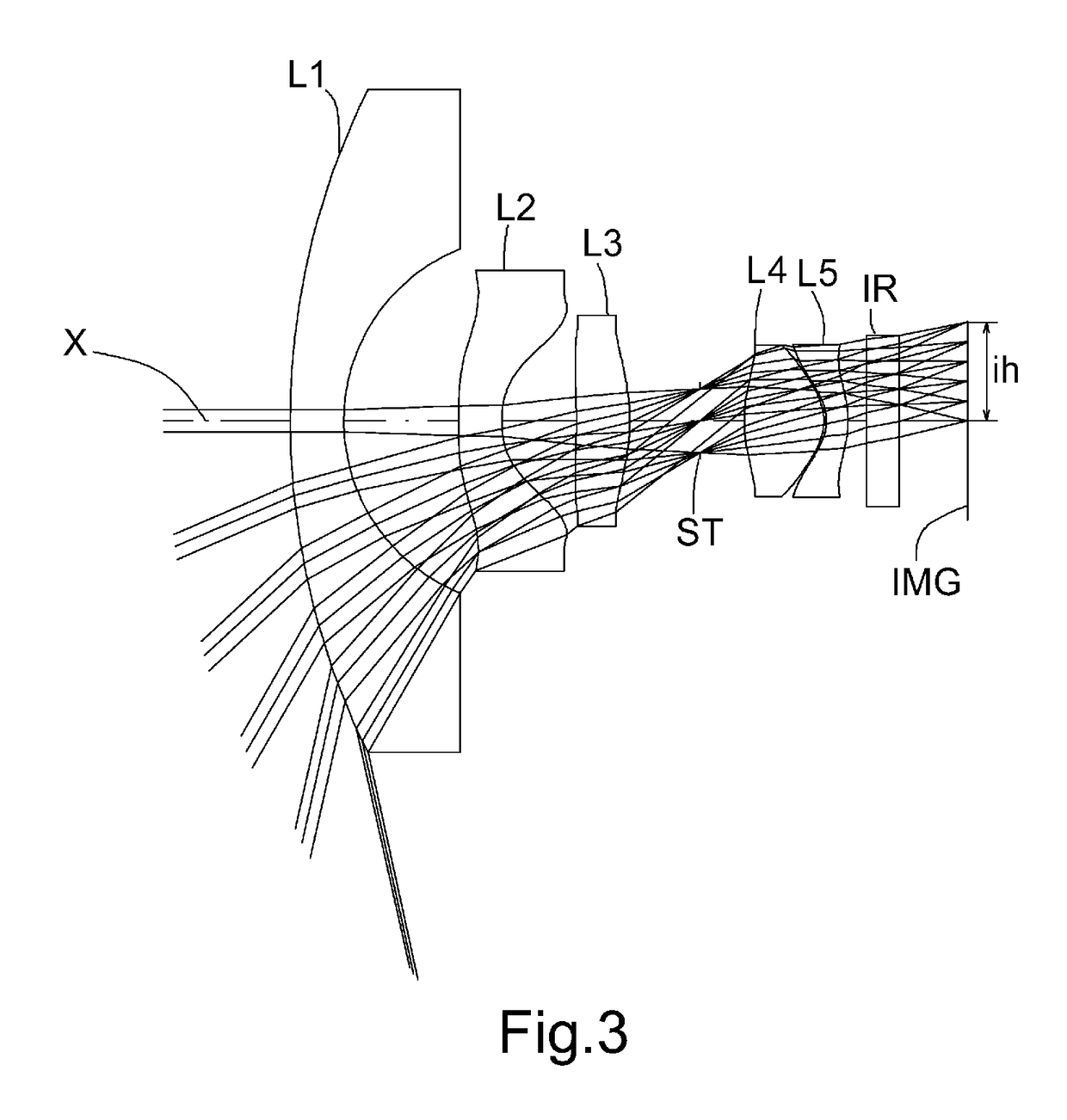
example 2
[0076]The basic lens data is shown below in Table 2.
TABLE 2Example2Unit mmf = 0.87Fno = 2.0ω(°) = 102.5ih = 1.85TTL = 12.45Surface DataSurfaceCurvatureSurfaceRefractiveNumber iRadius rDistance dIndex NdAbbe Numbervd(Object)InfinityInfinity 1InfinityInfinity 214.03291.00001.74349.22( vd1) 33.47932.1460 4*18.19560.80371.54455.86( vd2) 5*1.80001.4041 6*−9.14900.99871.66120.37( vd3) 7*−3.37001.30638(Stop)Infinity0.8339 9*3.05771.48871.69755.46( vd4) 10*−0.96780.0500 11*−0.79090.40001.66120.37( vd5) 12*−1.77360.349113Infinity0.61001.51764.1714Infinity1.2680Image PlaneInfinityConstituent Lens DataLensStart SurfaceFocal LengthComposite Focal Length12−6.486f12−1.89924−3.735f23−17.817367.555f341.516491.244f452.288511−2.578Aspheric Surface DataFourth SurfaceFifth SurfaceSixth SurfaceSeventh SurfaceNinth SurfaceTenth Surfacek 0.000000E+00−6.400111E+00 0.000000E+00 0.000000E+00 0.000000E+00−7.616447E−01A4 4.794071E−02 1.936259E−01 2.651053E−02 3.293261E−02 5.650915E−03 1.282899E−01A6−...
example 3
[0079]The basic lens data is shown below in Table 3.
TABLE 3Example3Unit mmf = 0.90Fno = 2.0ω(°) = 101.7ih = 1.85TTL = 12.77Surface DataSurfaceCurvatureSurfaceRefractiveNumber iRadius rDistance dIndex NdAbbe Numbervd(Object)InfinityInfinity 1InfinityInfinity 213.43551.00001.71353.94( vd1) 33.02572.0351 4*10.01880.80001.54455.86( vd2) 5*1.80001.5802 6*−4.72031.17111.66120.37( vd3) 7*−2.82651.14828(Stop)Infinity0.6739 9*2.69921.75101.59267.02( vd4) 10*−0.88010.0581 11*−0.76090.40001.66120.37( vd5) 12*−1.59150.421513Infinity0.61001.51764.1714Infinity1.3318Image PlaneInfinityConstituent Lens DataLensStart SurfaceFocal LengthComposite Focal Length12−5.705f12−1.92224−4.174f23−23.668368.557f341.478491.370f452.536511−2.730Aspheric Surface DataFourth SurfaceFifth SurfaceSixth SurfaceSeventh SurfaceNinth SurfaceTenth Surfacek 0.000000E+00−8817586E+00 0.000000E+00 0.000000E+00 0.000000E+00−8.822740E−01A4 6.078313E−02 2.612876E−01 7.295287E−03 1.545673E−02 3.478454E−03 1.940165E−01A6−1...
PUM
 Abstract
Description
Claims
Application Information
 - R&D
- Intellectual Property
- Life Sciences
- Materials
- Tech Scout
- Unparalleled Data Quality
- Higher Quality Content
- 60% Fewer Hallucinations
Browse by: Latest US Patents, China's latest patents, Technical Efficacy Thesaurus, Application Domain, Technology Topic, Popular Technical Reports.
© 2025 PatSnap. All rights reserved.Legal|Privacy policy|Modern Slavery Act Transparency Statement|Sitemap|About US| Contact US: help@patsnap.com