Supersonic inspection jig and supersonic inspection method

Active Publication Date: 2019-03-28
MITSUBISHI HEAVY IND LTD
View PDF0 Cites 2 Cited by
  • Summary
  • Abstract
  • Description
  • Claims
  • Application Information

AI Technical Summary

Benefits of technology

The invention provides a tool and method for inspecting the area around a hole easily using supersonic waves.

Problems solved by technology

Therefore, the detection signal is not stable when the state that the position of the probe and the position of the hole do not overlap and the state that the position of the probe and the position of the hole overlap switch frequently.
However, in this case, there is a fear that the inspection of the area around the hole becomes insufficient.

Method used


Image

  • Supersonic inspection jig and supersonic inspection method
  • Supersonic inspection jig and supersonic inspection method
  • Supersonic inspection jig and supersonic inspection method

Examples


embodiment

(Superonic Inspection Jig In Embodiment)

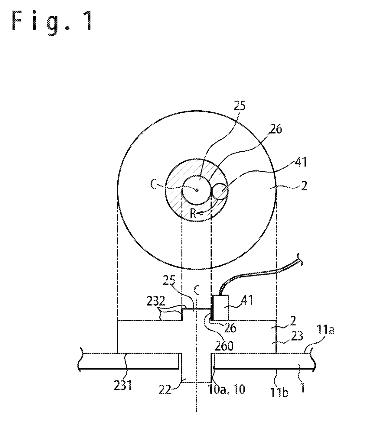
[0040]Referring to FIG. 1, a supersonic inspection jig 2 in the embodiment will be described. The upper part of FIG. 1 shows a plan view and the lower part thereof shows a side cross sectional view.

[0041]The supersonic inspection jig 2 is a jig used to inspect the periphery of a hole of an inspection target 1, i.e. an area around a hole 10. For example, the area around the hole 10 is an area in which the distance from the edge of the hole 10 is in a range of 0 mm to 100 mm. For example, the inspection target 1 is a board made from glass fiber reinforced plastic (FRP) having the hole 10. For example, the hole 10 is a hole in which a fastener for fastening is inserted. In an example shown in FIG. 1, the cross section shape of the hole (a shape in a plane perpendicular to a central axis C of the hole) is truly circular. However, the cross section shape of the hole may be a shape different from truly circular, e.g. an oval or an ellipse. Also, in ...

first modification example

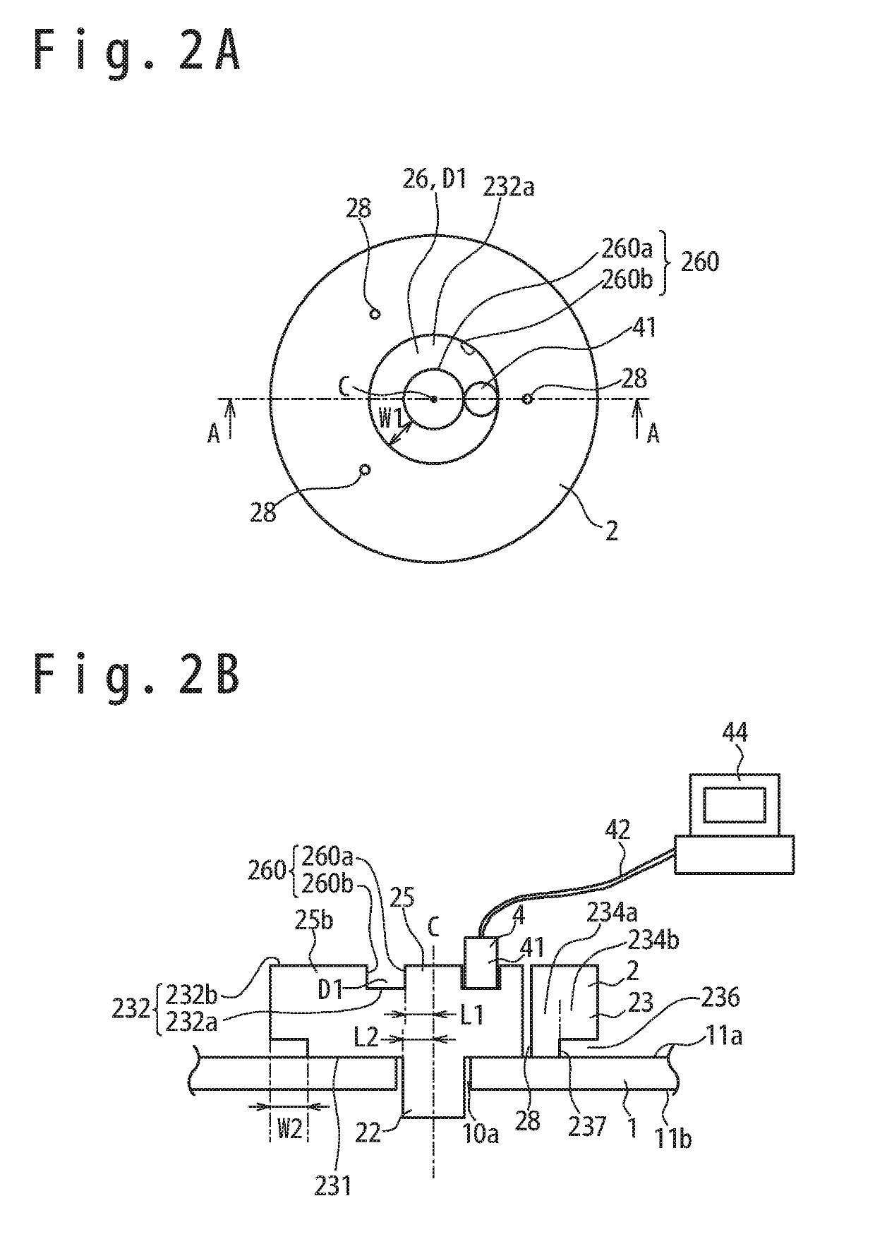
[0049]Referring to FIG. 2A and FIG. 2B, the supersonic inspection jig 2 in a first modification example will be described. FIG. 2A is a schematic plan view showing the supersonic inspection jig in the first modification example. Also, FIG. 2B is a cross sectional view of of the supersonic inspection jig along the A-A line in FIG. 2A.

(First Annular Concave Section D1)

[0050]In the supersonic inspection jig 2 in the first modification example, the position limiting section 26 is a first annular concave section D1. The first annular concave section D1 is a concave section that is defined by a first annular wall surface 260a, a concave section bottom surface 232a and a second annular wall surface 260b.

[0051]The first annular concave section D1 defines an annular orbit on which the probe 41 is movable. The first annular wall surface 260a is an outer circumference surface of the first protruding section 25, and prevents the probe 41 from moving to the direction approaching the central axi...

second modification example

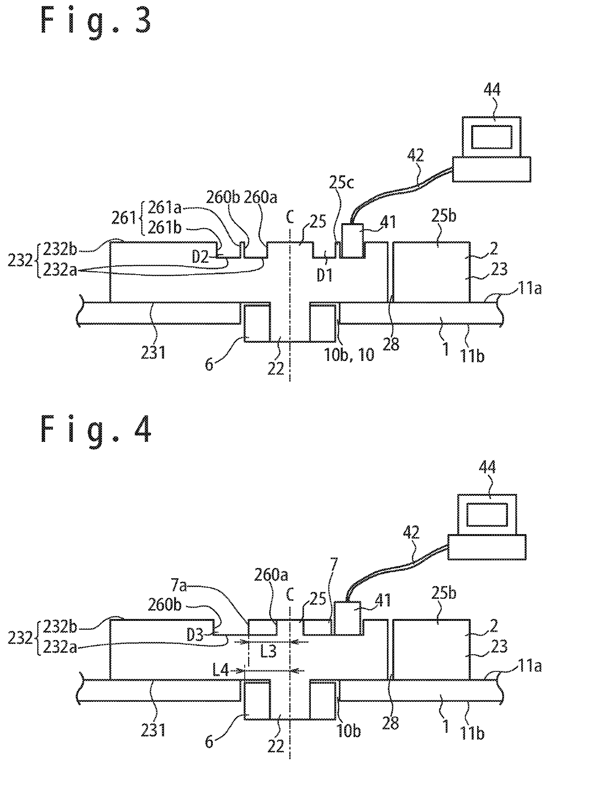
[0061]Referring to FIG. 3, the supersonic inspection jig 2 according to a second modification example will be described. FIG. 3 is a schematic cross sectional view showing the supersonic inspection jig 2 in the second modification example.

Second Position Limiting Section

[0062]The supersonic inspection jig 2 in the second modification example has a second position limiting section 261 which is different from the first annular concave section D1.

[0063]The second position limiting section 261 is a position limiting section different from the first annular concave section D1 as the first position limiting section. The movement orbit of the probe 41 guided by using the second position limiting section 261 is different from that of the probe 41 guided by using the first annular concave section D1. In the example shown in FIG. 3, the second position limiting section 261 is on the outer circumference side than the first annular concave section D1. Therefore, when the area around the relativ...


PUM


Abstract

A supersonic inspection jig has an insertion section 22 inserted into a hole 10 of an inspection target 1, and a flange section 23 connected with the insertion section 22 and contacting the inspection target 1. The flange section 23 has a flange section first surface 231 which is a surface on the side contacting the inspection target 1 and a flange section second surface 232 which is a surface on the side contacting the probe 41. A position limiting section 26 is provided on the flange section second surface 232 to limit the position of the probe 41 so that the probe 41 is maintained in a position separate from a central axis C of the hole 10. Thus, the inspection around the hole becomes easily executable.

Description

TECHNICAL FIELD[0001]The present invention relates to a supersonic inspection jig and a supersonic inspection method, and especially, to an inspection jig of an area around a hole used in a supersonic inspection and a supersonic inspection method of the area around the hole.BACKGROUND ART[0002]It is supposed that an inspection target having a hole is inspected by using a supersonic probe. A supersonic wave detection signal detected by a probe when the position of a supersonic wave emitting surface of the probe and the position of the hole overlap, and the supersonic wave detection signal detected by the probe when the position of the supersonic wave emitting surface of the probe and the position of the hole do not overlap are different mainly each other. Therefore, the detection signal is not stable when the state that the position of the probe and the position of the hole do not overlap and the state that the position of the probe and the position of the hole overlap switch frequen...

Claims


Application Information

Patent Timeline
IPC IPC(8): G01N29/265G01N29/28
CPCG01N29/265G01N29/28G01N2291/0231G01N2291/0232G01N2291/0235G01N2291/2636G01N29/043G01N29/221G01N29/2462G01N29/2487G01N2291/044G01N2291/101
Inventor TAKEMOTO, HIROSHIKUZE, YOSHIHARUUEMATSU, MITSUYOSHIKOBAYASHI, SEIJI
Owner MITSUBISHI HEAVY IND LTD
Why Eureka
Try Eureka