Pattern inspection device and pattern inspection method

Inactive Publication Date: 2013-04-18
HOYA CORP
View PDF1 Cites 1 Cited by
  • Summary
  • Abstract
  • Description
  • Claims
  • Application Information

AI Technical Summary

Benefits of technology

The invention makes it easier to inspect patterns on disk media compared to using a scanning electron microscope.

Problems solved by technology

However, when producing a disk media with patterns, misalignment or dimensional variation could possibly occur in the finally-obtained bit patterns due to various factors during the lithography (exposure and development) process, or before and after the lithography process.
Therefore, if a disk medium having the bit patterns which are misaligned or varied in size beyond the clearance level is used for the base and imprinting, defective products are produced frequently.

Method used


Image

  • Pattern inspection device and pattern inspection method
  • Pattern inspection device and pattern inspection method
  • Pattern inspection device and pattern inspection method

Examples


Embodiment Construction

[0037]Hereafter, embodiments of the present invention will be described in detail with reference to the drawings.

[0038]The embodiments of the present invention will be described in the following order:

[0039]1. Configuration of pattern inspection device

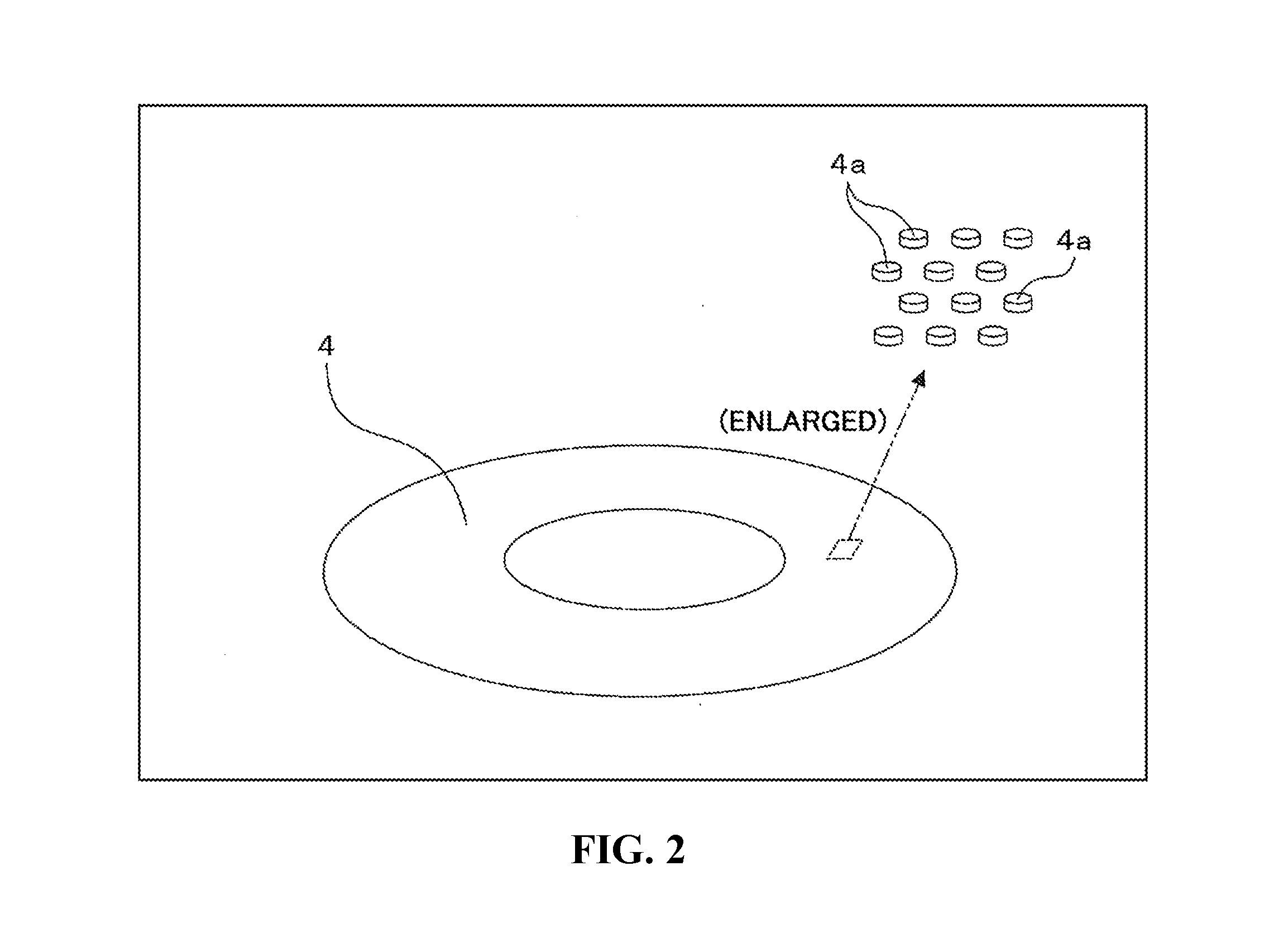
[0040]2. Structure of disk medium

[0041]3. Pattern inspection method

[0042]4. Effects of the embodiments

[0043]5. Modifications

[0044]

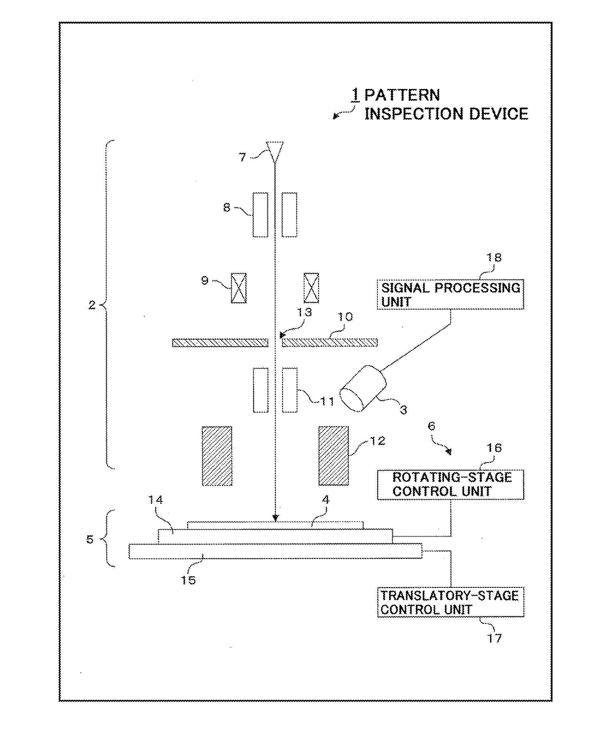
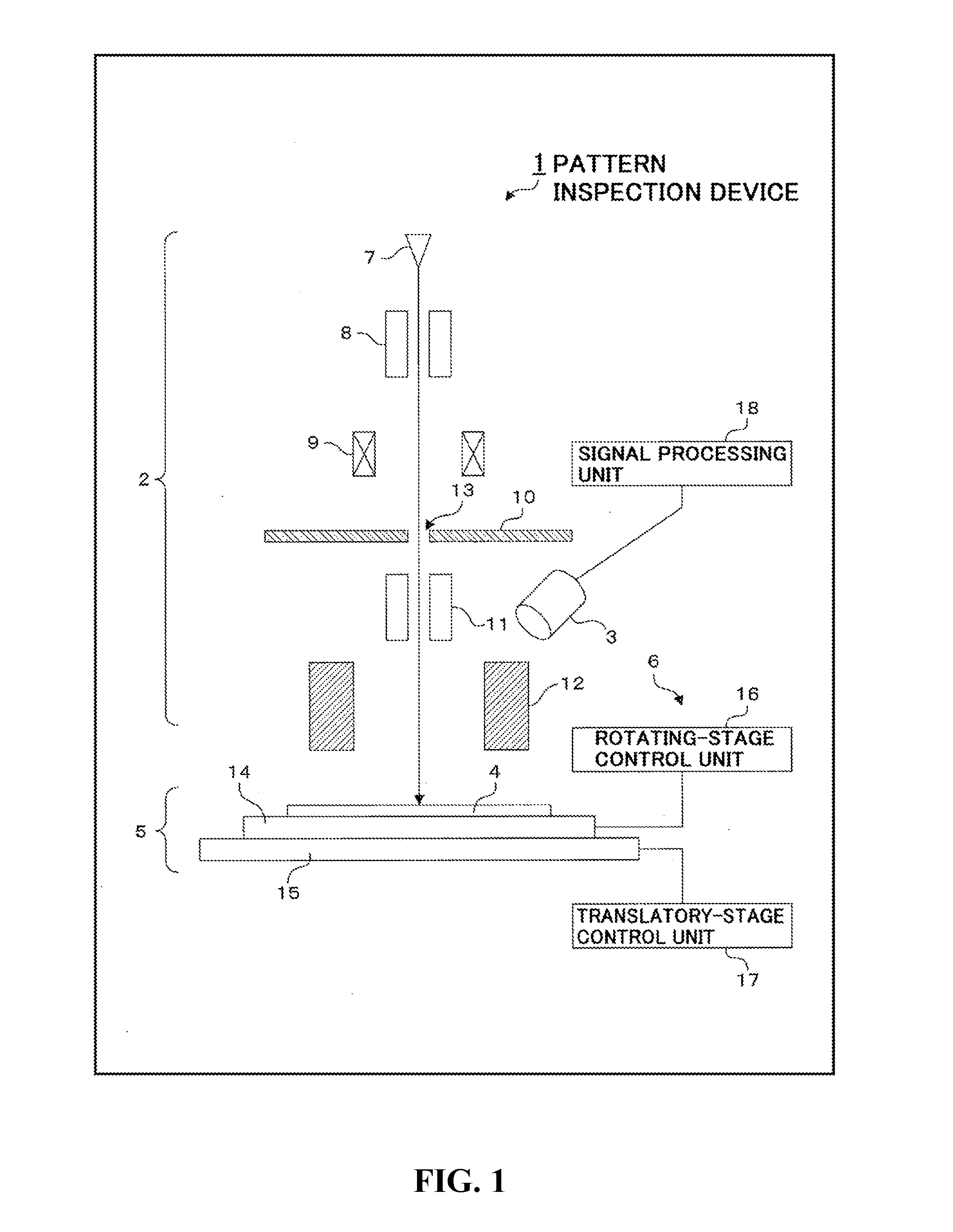
[0045]FIG. 1 is a schematic diagram showing a configuration example of a pattern inspection device according to an embodiment of the present invention. The illustrated pattern inspection device 1 mainly includes an irradiating optical system 2 for radiating an electron beam, an electron detector 3 for detecting an electron, a stage mechanism 5 for supporting a disk medium 4 which is a pattern inspection target, and a stage control system 6 for controlling the drive of the stage mechanism 5.

[0046](Configuration of Irradiating Optical System)

[0047]The irradiating optical system 2 irradiates the disk medium 4 p...


PUM


Abstract

Disclosed is a pattern inspection device for inspecting a bit pattern of a disk medium having a plurality of tracks which are concentrically formed on the disk medium, the bit pattern on each track being spaced for each bit in radial and circumferential directions, the pattern inspection device including: a rotating stage on which the disk medium is placed; an irradiating optical system for radiating an electron beam onto the disk medium that rotates together with the rotating stage; and an electron detector for detecting electrons generated from the disk medium on the rotating stage by the irradiation of the electron beam of the irradiating optical system, wherein a spot diameter of the electron beam of the irradiating optical system is set not less than a diameter of the bit pattern.

Description

TECHNICAL FIELD[0001]The present invention relates to a pattern inspection device and a pattern inspection method that are applied when inspecting patterns formed on a disk medium.BACKGROUND ART[0002]As one of disk media used for magnetic recording and reproducing apparatuses, such as hard disk drive units, a disk medium that is called a “bit patterned medium” has been known. A plurality of recording tracks are concentrically formed on this kind of disk medium. Patterns constituting each track are spaced for each bit in the radial and circumferential directions of the disk medium. In this specification, a pattern that is spaced for each bit, as stated above, is called a “bit pattern”.[0003]Recently, an “imprint technique” has been utilized as a technique for forming the patterns on a disk medium. In the imprint technique, concavo-convex patterns are formed on a base disk medium called a stamper, and the concave and convex of the concavo-convex patterns are transferred from the stamp...

Claims


Application Information

Patent Timeline
IPC IPC(8): H01J37/26
CPCG11B5/855H01J37/244H01J37/26H01J2237/24592H01J2237/2817H01J37/252
Inventor YAMASHITA, HIROSHI
Owner HOYA CORP
Why Eureka
Try Eureka