Scanning optical system manufacturing method, beam inspection method, and beam inspection apparatus

Active Publication Date: 2013-03-21
CANON KK
View PDF8 Cites 0 Cited by
  • Summary
  • Abstract
  • Description
  • Claims
  • Application Information

AI Technical Summary

Benefits of technology

The present invention provides a simple way to inspect a scanning optical system using an inspection apparatus. The technical effect achieved is that this simplifies the process of inspecting the system, which can save time and reduce costs.

Problems solved by technology

Since it is not possible to ship such a product that produces density unevenness remarkably degrading image quality, an image-forming optical system or a scanning optical system involving an large spot diameter, even if it is local, is disposed of or re-adjusted before an assembly stage of an image forming apparatus.
However, since a relation between the spot diameter and the image density is not linear, some printed images have no problem even if the spot diameter exceeds an inspection value, and other printed images have density unevenness even if the spot diameter does not exceed the inspection value.
On the other hand, the method for measuring a spot diameter has a problem that measurement takes time.

Method used


Image

  • Scanning optical system manufacturing method, beam inspection method, and beam inspection apparatus
  • Scanning optical system manufacturing method, beam inspection method, and beam inspection apparatus
  • Scanning optical system manufacturing method, beam inspection method, and beam inspection apparatus

Examples


Embodiment Construction

[0027]Various exemplary embodiments, features, and aspects of the invention will be described in detail below with reference to the drawings.

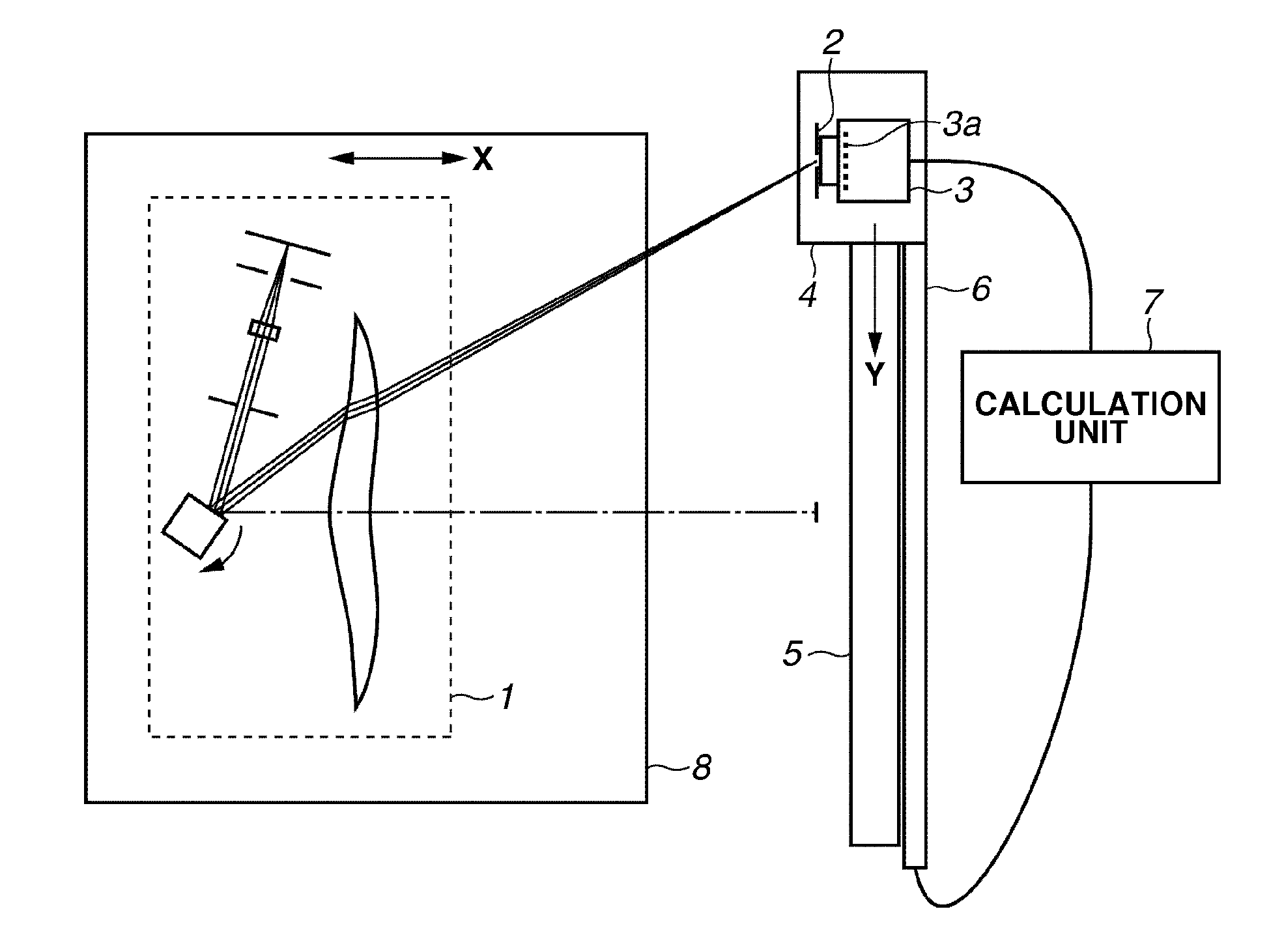
[0028]Prior to descriptions of exemplary embodiments of the present invention, technical terms used in this specification will be predefined. In this specification, the term “main scanning direction” means a direction in which a light beam emitted from a scanning optical system is deflected for scanning, and the term “sub scanning direction” means a direction perpendicularly intersecting with the main scanning direction and with an optical axis direction of the scanning optical system. The term “image plane” means a flat surface on which image bearing members are arranged in a scanning optical apparatus using the scanning optical system. This term does not include the meaning of the curvature of the image plane.

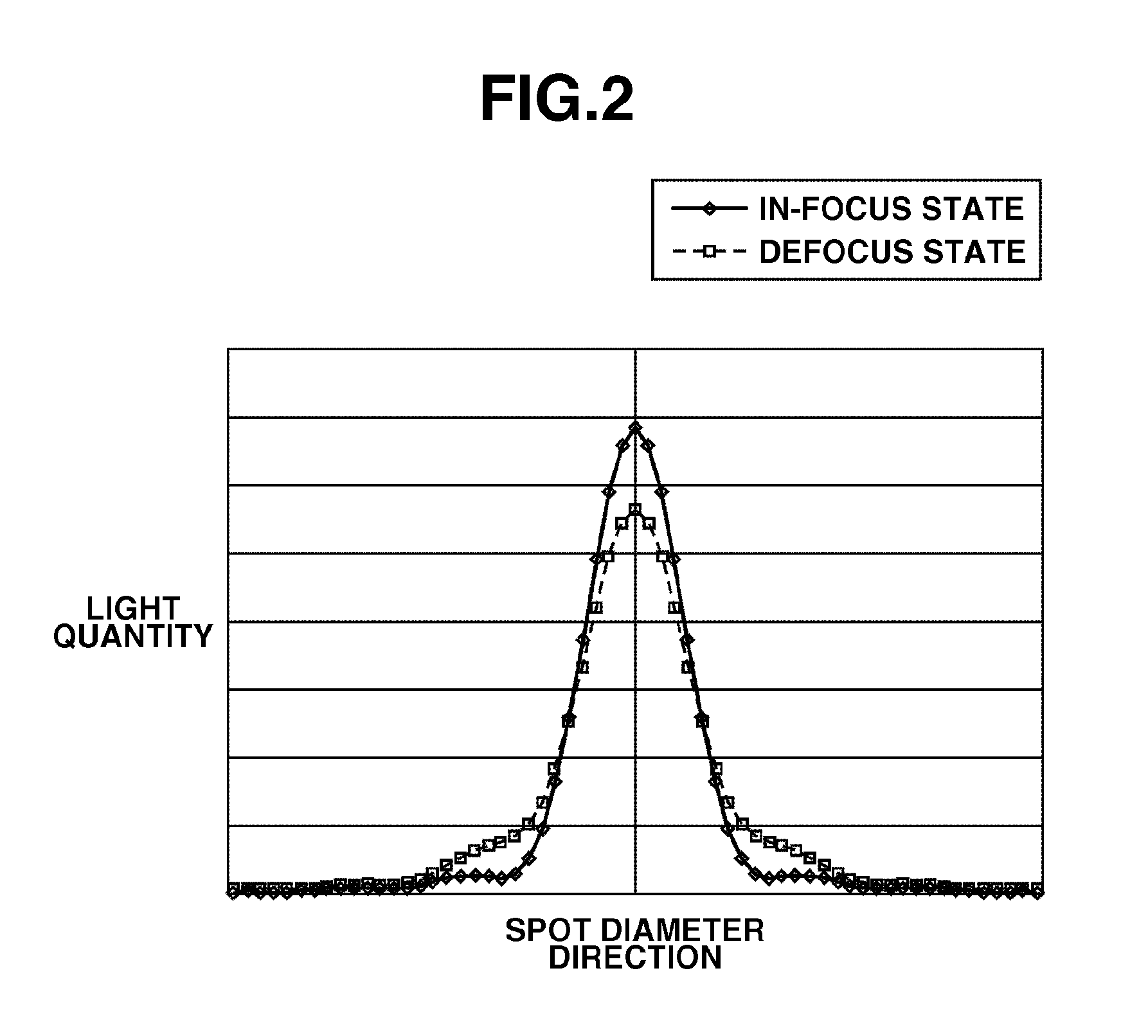
[0029]In the present invention, the term “spot diameter” means a diameter of an area equal to or more than 1 / ê2 times the maximum valu...


PUM


Abstract

A scanning optical system manufacturing method includes receiving a scanning beam, emitted from a scanning unit including an incident optical system and a deflecting device and passed through an image-forming optical system, in an area having a width in the main scanning direction narrower than a spot diameter of the scanning beam by a light-receiving unit configured to be capable of being displaced at each image height position in the main scanning direction, calculating, based on an output of the light-receiving unit, a peak light quantity at each image height position of the scanning beam, smoothing distribution data of the peak light quantity at each of the image height position acquired by the calculating, and determining, based on the data acquired by the smoothing, either nondefective / defective states of the scanning unit and the image-forming optical system or a nondefective / defective state of only the image-forming optical system.

Description

BACKGROUND OF THE INVENTION[0001]1. Field of the Invention[0002]The present invention relates to a scanning optical system manufacturing method, and a beam inspection method and an beam inspection apparatus.[0003]2. Description of the Related Art[0004]Conventionally, spot diameter measurement has been performed as a part of optical performance evaluation of an image-forming optical system or a scanning optical system including the image-forming optical system. Generally, since an enlarged spot diameter reduces a peak light quantity of a beam spot, a printed image has a tendency of providing a low density at an image height having an enlarged spot diameter. Since it is not possible to ship such a product that produces density unevenness remarkably degrading image quality, an image-forming optical system or a scanning optical system involving an large spot diameter, even if it is local, is disposed of or re-adjusted before an assembly stage of an image forming apparatus.[0005]Japanese...

Claims


Application Information

Patent Timeline
IPC IPC(8): G01J1/44
CPCG01J1/44G01J1/16G01J2001/444H04N1/00018
Inventor YOSHIDA, HIROKI
Owner CANON KK
Why Eureka
Try Eureka