

High fiber count package foam insert
- Summary
- Abstract
- Description
- Claims
- Application Information
AI Technical Summary
Benefits of technology
Problems solved by technology
Method used
Image

Examples
Embodiment Construction
[0024]Hereinafter the non-limiting exemplary embodiments of the present invention will be described in detail with reference to the accompanying drawings.
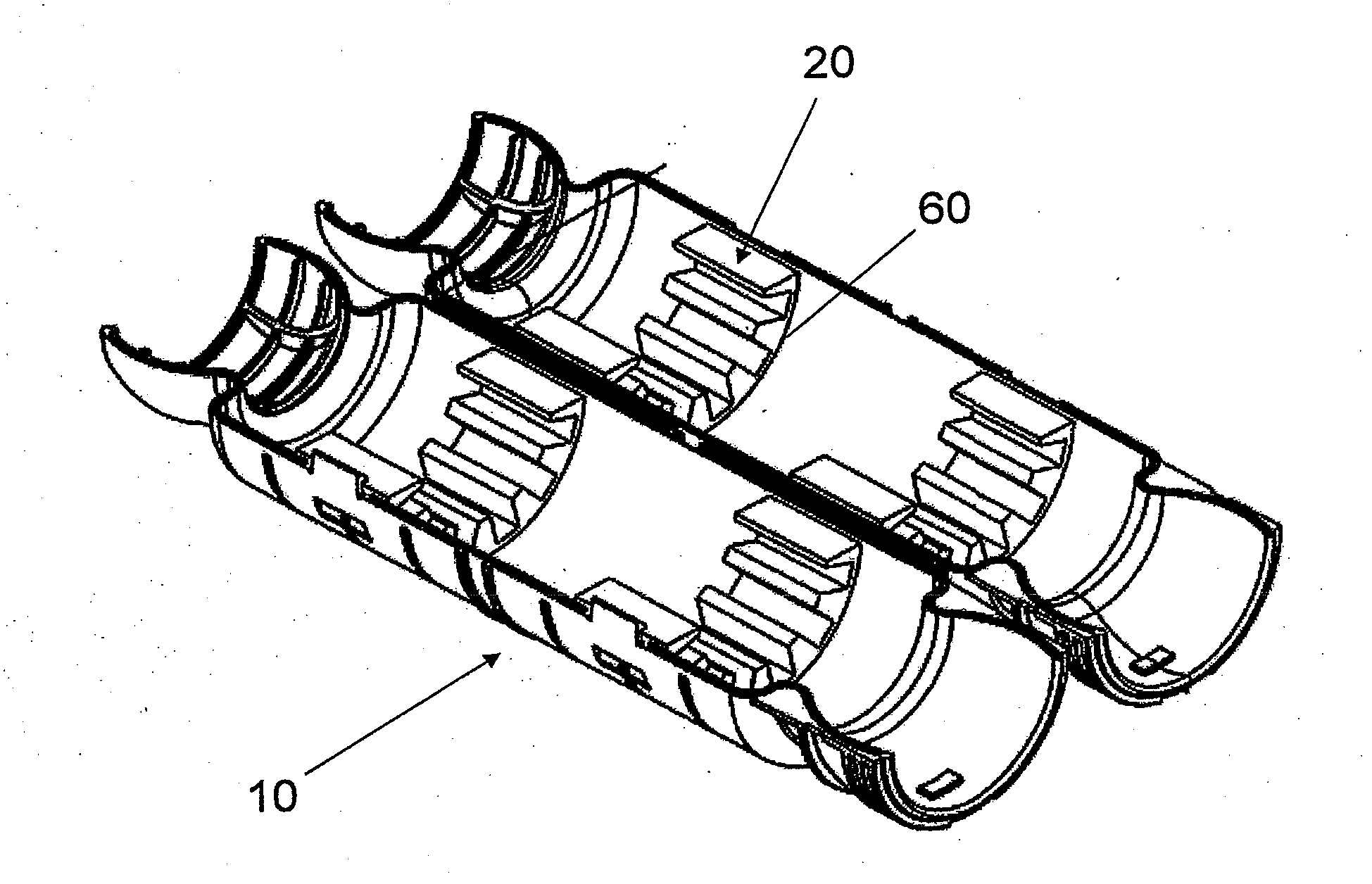
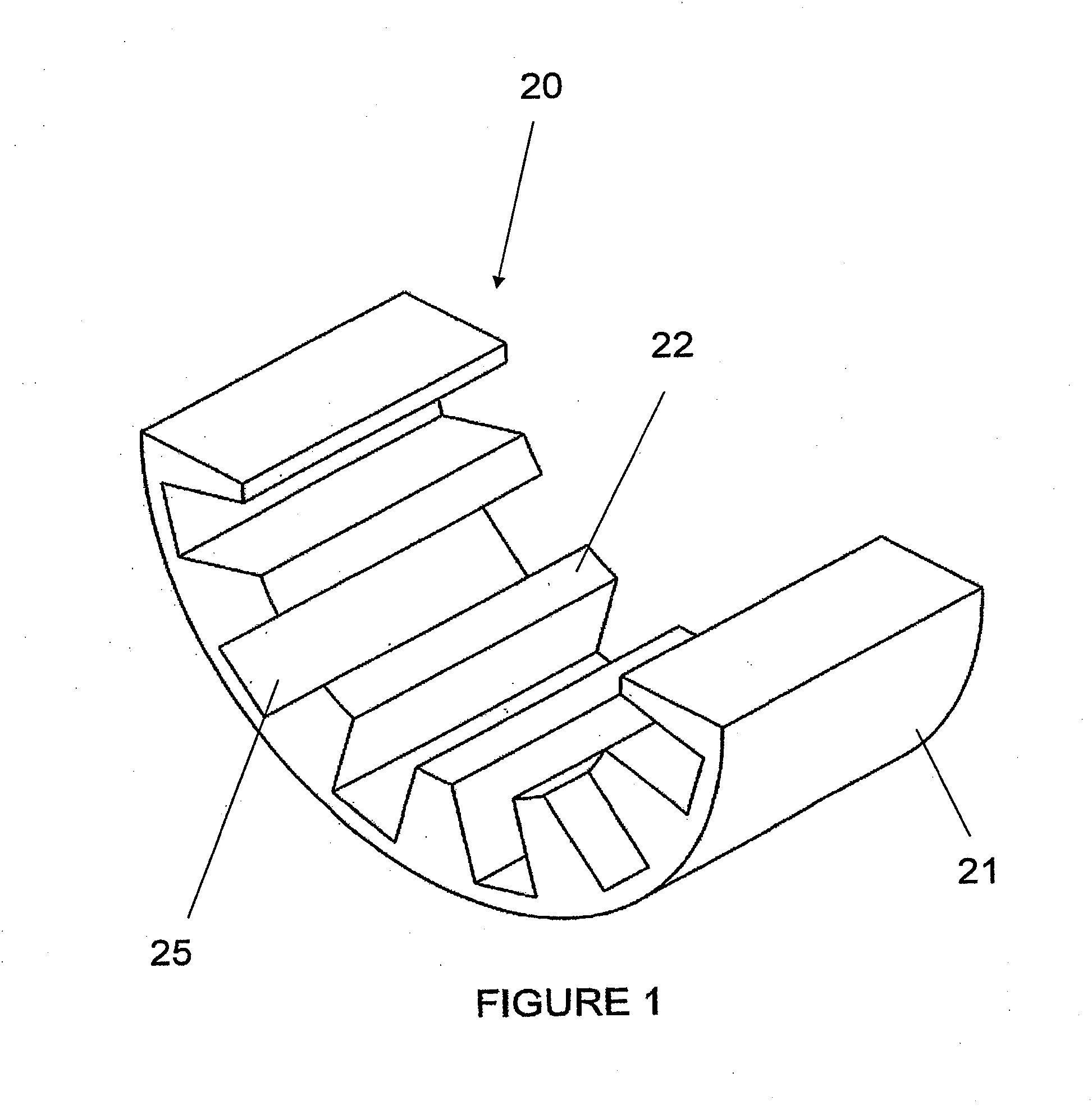
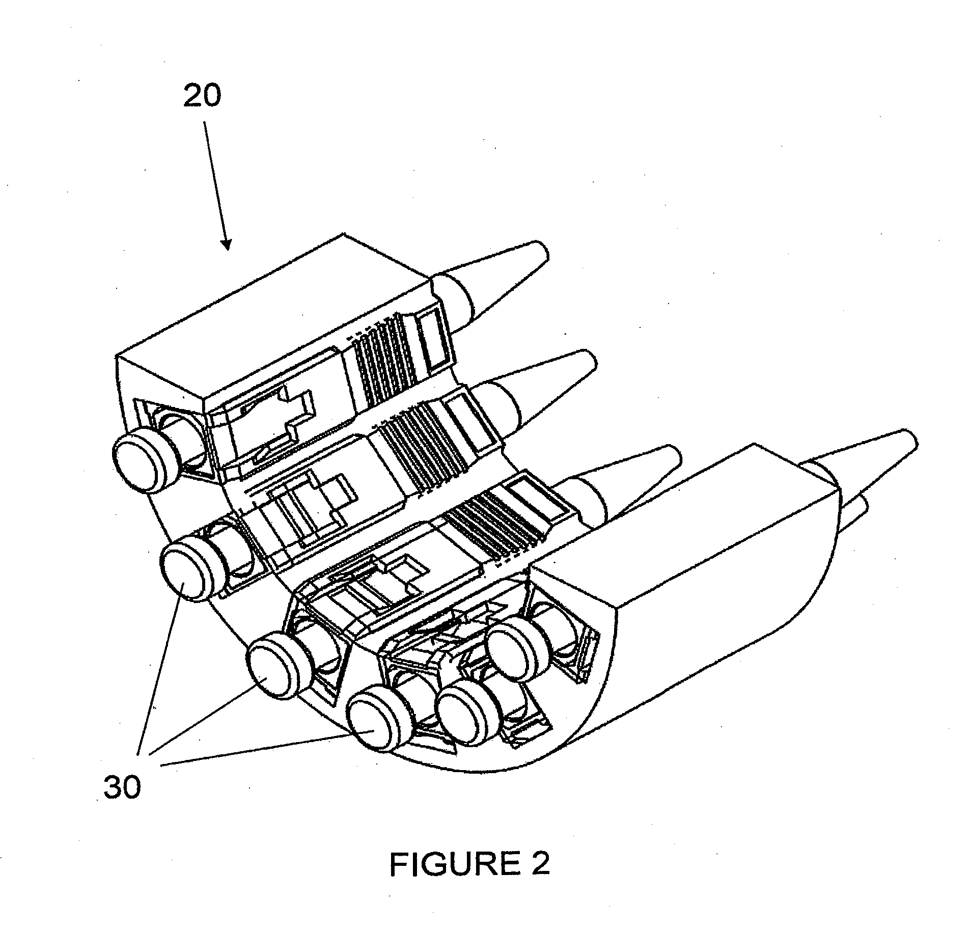
[0025]The first exemplary embodiment is shown in FIGS. 1 and 2. FIG. 1 shows a foam insert 20 made of a foam material. While the material in this embodiment is described as a foam or foam material, any other low density compressible material having compressibility that enables it to conform to and hold a connector may be used. Also, by using a low density material, the amount of deformation permitted by the foam insert 20 is large enough to enable the foam insert 20 to receive and hold fiber optic connectors 30 of different shapes and sizes.
[0026]The foam insert 20 has an outer side surface 21 that is configured to be fitted into and received by a fiber packing module 10 (see FIG. 5). In this embodiment, the outer side surface 21 has a cylindrical shape having a cross section of a half circle. The inside surface 22 is formed with m...
PUM
 Abstract
Description
Claims
Application Information