
Chain Link Tester

Active Publication Date: 2014-09-11
R J REYNOLDS TOBACCO COMPANY
View PDF0 Cites 0 Cited by
  • Summary
  • Abstract
  • Description
  • Claims
  • Application Information

AI Technical Summary

Benefits of technology

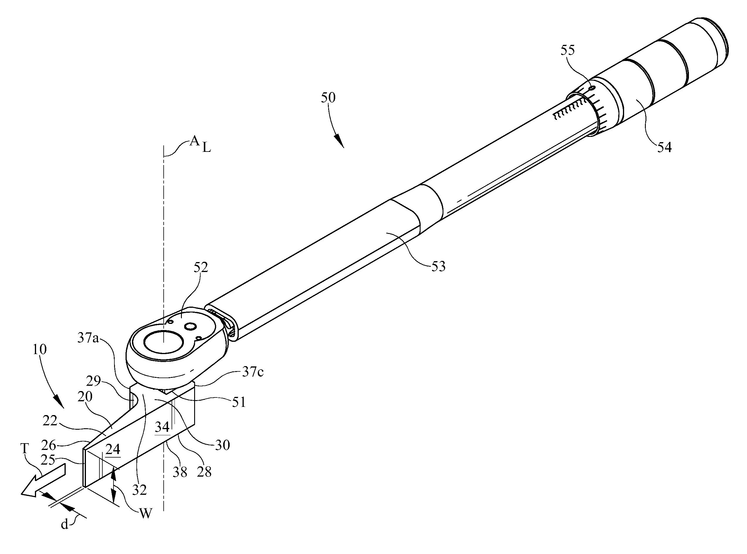
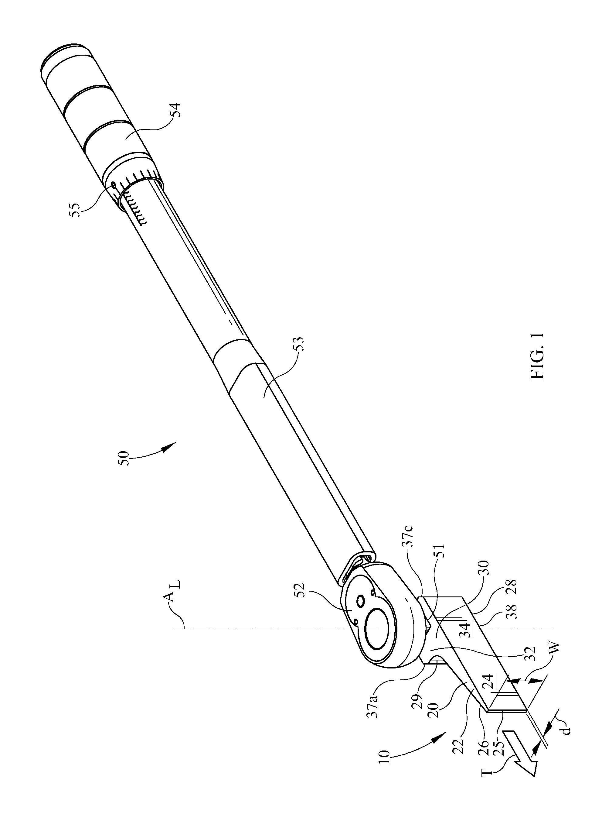
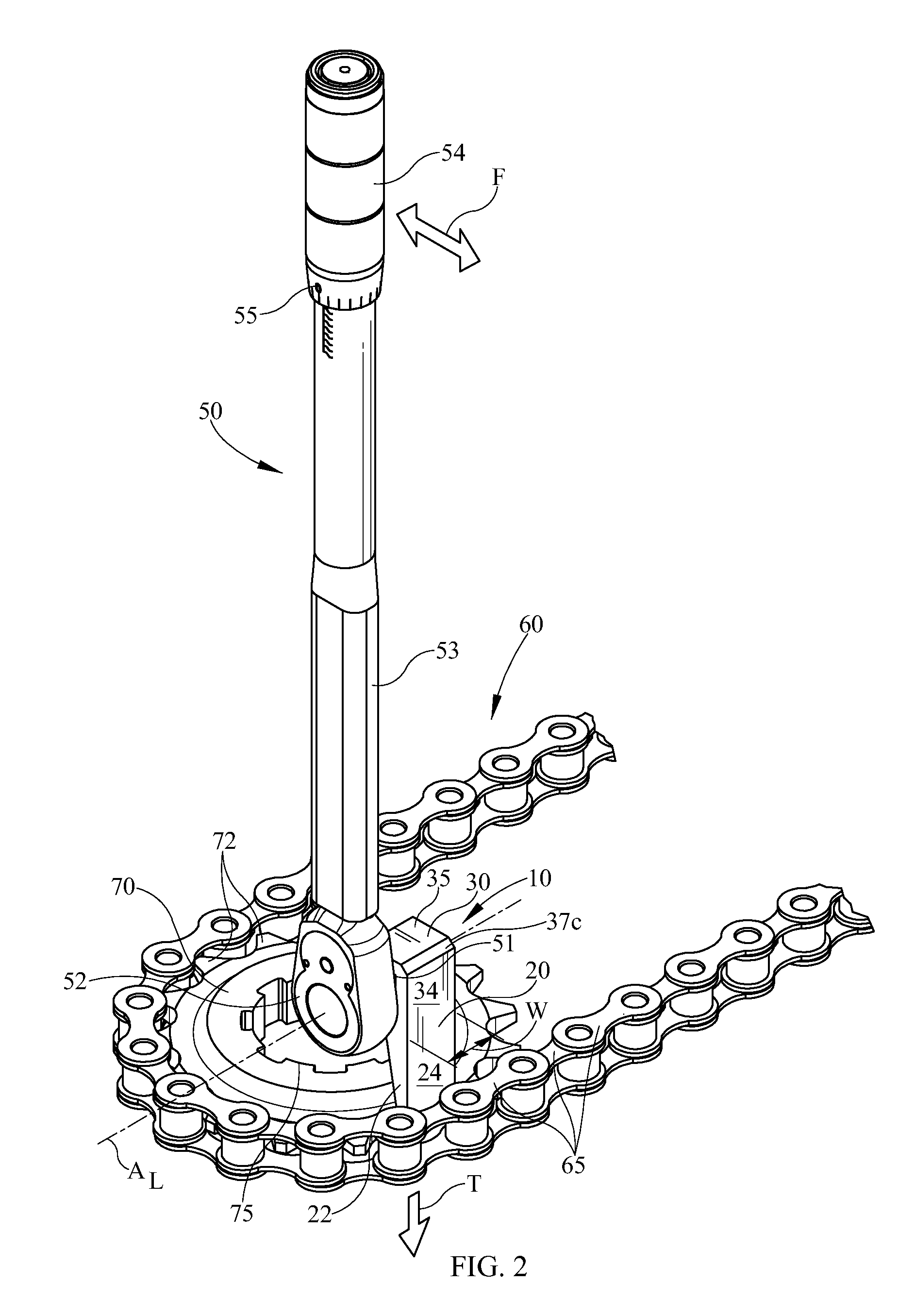
The present invention provides a chain link tester for testing and inspecting the integrity of individual chain links in a chain, particularly in applications such as industrial conveyor belts, where chains may be very long. The chain link tester is adapted for use with a torque metering device, such as a torque wrench or torque ratchet, which indicates when a predetermined amount of torque has been applied to each chain link, ensuring consistent amounts of torque are applied to each link. The chain link tester is designed to fit and wedge between the chain links and the mechanism driving the chain, such as a sprocket, to enhance the consistency and effectiveness of the test. This invention facilitates the testing and inspection of chain links, making it easier and more efficient to ensure the chain is operating properly and safely.

Problems solved by technology

However, chains in use in some applications, such as, for example, those in use in industrial conveyor belts, may be very long.
It may be difficult to consistently and efficiently test a large number of chain links due to, for example, operator fatigue.

Method used


Image

  • Chain Link Tester
  • Chain Link Tester
  • Chain Link Tester

Examples


Embodiment Construction

[0014]It is to be understood that the various embodiments described herein are not limited in their application to the details of construction and the arrangement of components set forth in the following description or illustrated in the drawings. Also, it is to be understood that the phraseology and terminology used herein is for the purpose of description and should not be regarded as limiting. The use of “including,”“comprising,” or “having” and variations thereof herein is meant to encompass the items listed thereafter and equivalents thereof as well as additional items. Unless limited otherwise, the terms “connected,”“coupled,”“in communication with” and “mounted,” and variations thereof herein are used broadly and encompass direct and indirect connections, couplings, and mountings. In addition, the terms “connected” and “coupled” and variations thereof are not restricted to physical or mechanical connections or couplings.

[0015]Furthermore, and as described in subsequent paragr...


PUM


Abstract

A chain link tester and method of use is disclosed herein. The chain link tester may contain a tapered lever and may be adapted to operatively connect to a torque metering device. The chain link tester may be used to test chain links.

Description

FIELD OF THE INVENTION[0001]The present invention is related generally to tools for testing equipment, and more specifically to a chain link testing device for chain links.BACKGROUND OF THE INVENTION[0002]It is often desirable to drive a conveyor belt using a chain-and-sprocket mechanism or drive. A chain-and-sprocket drive may be used in any of a variety of applications. Some examples of applications that may employ a chain-and-sprocket drive relate to converting materials from small fibers or pieces into a sheet, mat, or web for processing. One way to do this is to mix the fibers or pieces with water or other liquid into a slurry and then pour the slurry onto a surface so that it may settle into the desired form, which may be a sheet, mat, or web (hereinafter “web”). The extra water or other liquid (hereinafter “liquid”) may then be allowed to dry off, leaving the small fibers or pieces congealed together in the desired web form. In order to decrease the drying time required, and ...

Claims


Application Information

Patent Timeline
IPC IPC(8): G01N3/22
CPCG01N3/22G01M13/023
Inventor TILLEY, TIMOTHY
Owner R J REYNOLDS TOBACCO COMPANY
Learn More