Systems and methods for electrical inspection of flat panel displays using cell contact probing pads

Active Publication Date: 2017-05-25
ORBOTECH LTD
View PDF6 Cites 7 Cited by
  • Summary
  • Abstract
  • Description
  • Claims
  • Application Information

AI Technical Summary

Benefits of technology

[0030]In accordance with another aspect of the embodiments described herein, there is provided a method for facilitating inspection of a device under test comprising a plurality of panels, the method involving: configuring a universal probe bar by positioning a plurality of probe blocks at predetermined locations along a universal mounting rail, the plurality of probe blocks comprising a plurality of probe pins,

Problems solved by technology

Nonetheless, many LCDs have to be discarded because of manufacturing flaws.
In small panel applications (e.g. mobile phone displays and tablets), this loss of real estate has serious implications for glass uti

Method used


Image

  • Systems and methods for electrical inspection of flat panel displays using cell contact probing pads
  • Systems and methods for electrical inspection of flat panel displays using cell contact probing pads
  • Systems and methods for electrical inspection of flat panel displays using cell contact probing pads

Examples


Example

[0046]In the following detailed description, reference will be made to the accompanying drawing(s), in which identical functional elements are designated with like numerals. The aforementioned accompanying drawings show by way of illustration, and not by way of limitation, specific embodiments and implementations consistent with principles of the present invention. These implementations are described in sufficient detail to enable those skilled in the art to practice the invention and it is to be understood that other implementations may be utilized and that structural changes and / or substitutions of various elements may be made without departing from the scope and spirit of present invention. The following detailed description is, therefore, not to be construed in a limited sense.

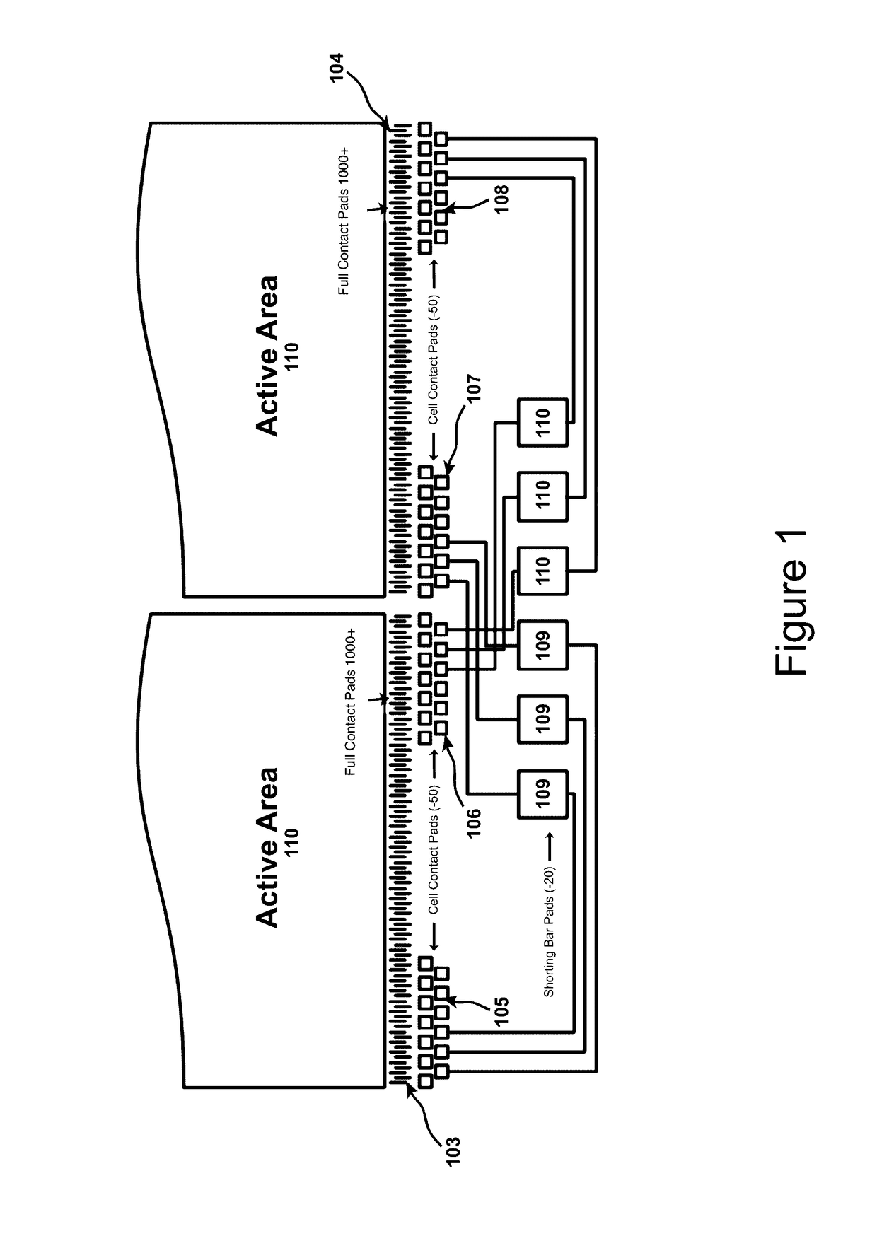
[0047]Currently, small displays are mostly tested using full contact electrical testers. This method requires no additional real estate for shorting bars because each drive line is contacted individually, ...


PUM


Abstract

A probe system for facilitating inspection of a device under test comprising a plurality of panels, the probe system incorporating: a configurable universal probe bar comprising a plurality of probe blocks, the plurality of probe blocks comprising a plurality of probe pins positioned to simultaneously electrically engage a plurality of cell contact pads of the plurality of panels of the device under test to deliver a plurality of electrical test signals; and an alignment system configured to achieve an alignment of the plurality of probe pins with the plurality of the cell contact pads of the plurality of panels of the device under test.

Description

CROSS-REFERENCE TO RELATED PATENT APPLICATION[0001]This regular U.S. patent application relies upon, and claims the benefit of priority from U.S. provisional patent application No. 62 / 259,075, entitled “Systems And Methods For Electrical Inspection Of Flat Panel Displays Using Cell Contact Probing Pads,” filed on Nov. 24, 2015, which is incorporated by reference herein in its entirety.BACKGROUND OF THE INVENTION[0002]Field of the Invention[0003]The present invention relates generally to the field of inspection of electronic devices and in particular to inspection of Liquid Crystal (LC) and Organic Light Emitting Diode (OLED) displays, and the mechanical, optical and electronic systems used in this inspection.[0004]Description of the Related Art[0005]Liquid crystal display (LCD) panels incorporate liquid crystals that exhibit electric-field dependent light modulating properties. They are used most frequently to display images and other information in a variety of devices ranging from...

Claims


Application Information

Patent Timeline
IPC IPC(8): G01R1/067G09G3/00G01R1/073
CPCG01R1/06794G09G3/006G01R1/07364G01R1/06722G01R1/07307G02F1/1309G02F1/13458
Inventor YUE, GORDONJONES, LLOYD RUSSELLNGUYEN, NEIL DANGJITENDRA, KIRANNGUYEN, KENTAOCHI, STEVEN
Owner ORBOTECH LTD
Why Eureka
Try Eureka